
|
|
|
#21
 10-08-2014, 06:52 PM
|
||||
|
||||
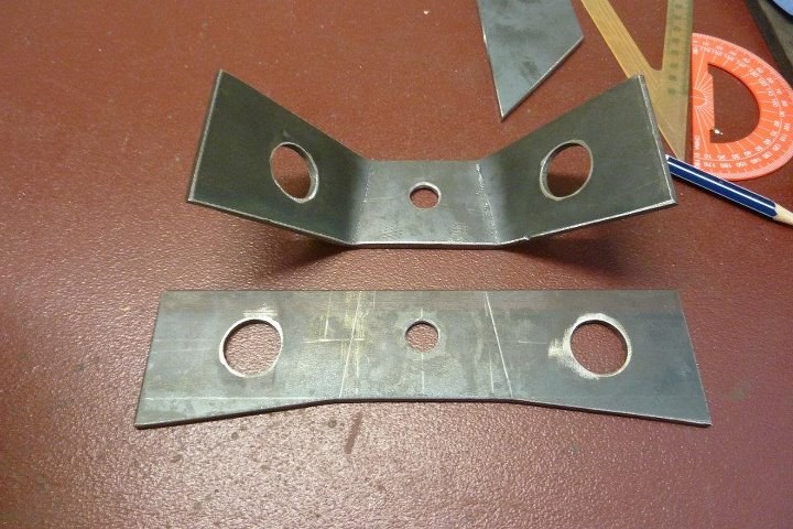 Just making up the outer support for the rear shock absorbers. This gives them what is called double shear support as supported on both sides. The folds were done at a 8* angle so I would end up with a 8* slope to match that of the threaded boss that has already been welded into the frame. 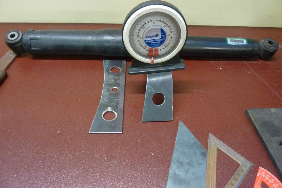 Here you can see the result. The face that the bolt goes through is at 8*. This is to match what was on the Grand Cherokee as the lower shock mounts on the axle are wider than on the chassis. I also added an extra 16* in the legs. The top would have tilted downwards 8* other wise and I added another 8* so it actually tilted upwards for a better look. 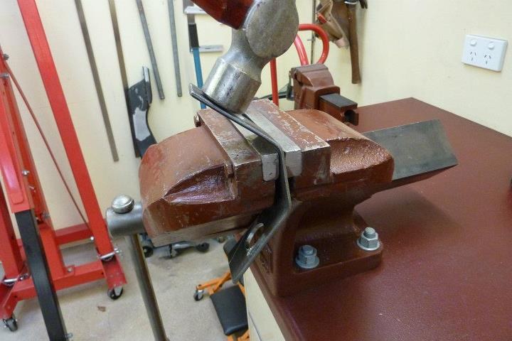 The folds were simply hammered over in a 6" offset bench vise so I would get a softer fold. I clamped the centre section for both folds as wanted that to remain as flat as possible.  I added holes in the support top plate as well as the legs to take the heaviness out of the bracket. 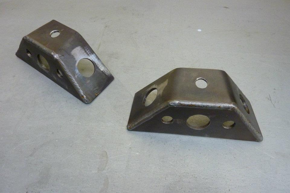 All welded up. Was going to grind and sand them smooth, but thinking I might just leave it as is? 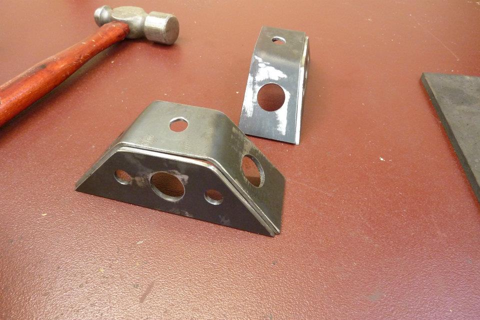 This how it will sit on the frame rail with the shock angle 8* outwards. Also will be angled similar to this to reach the axle which will be centred forward of the mount. 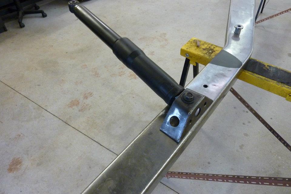 The bolt was only done up finger tight and had a piece of card placed in-between to allow for paint thickness. 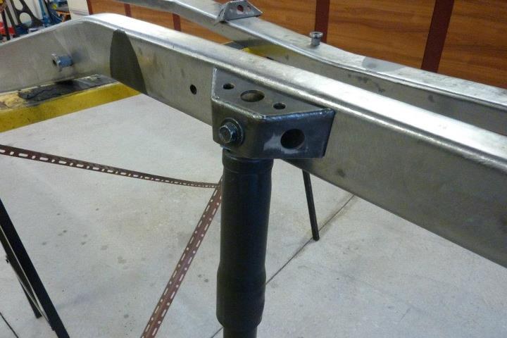 As nothing will be welded directly on the other side of the mount, it would cause bending as the weld starts to cool. So I used half of the old bumper that was on the Willys and some 1/4" flat centred over the mount and clamped it down. 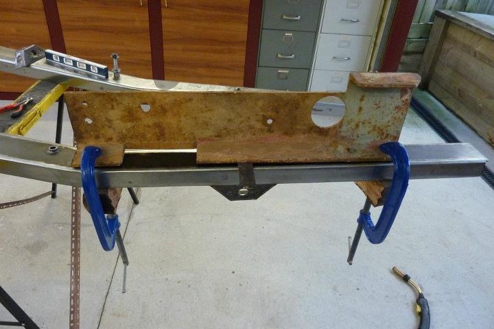 The pressure applied is in the reverse direction to which the welding will try to pull it. The weld will try to pull downwards and the clamps, with the flat underneath, is trying to bend it upwards. 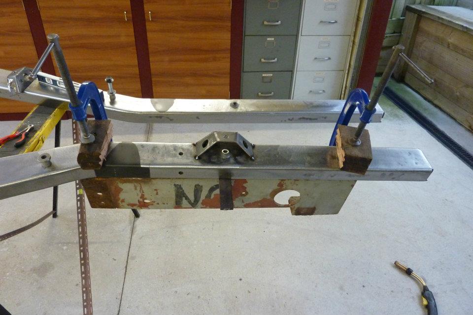 The tricked worked quite well with one side remaining perfectly straight and the other just moving a fraction, which I pressed out straight.
__________________
Marcus aka. Gojeep Victoria, Australia http://willyshotrod.com Invention is a combination of brains and materials. The more brains you use, the less materials you need. Last edited by Gojeep; 08-01-2017 at 03:00 AM. 
|
|
#22
10-08-2014, 10:14 PM
|
||||
|
||||
|
THAT your new tig at work marcus ?
__________________
David Geelong victoria Australia
|
|
#23
10-09-2014, 02:48 AM
|
||||
|
||||
|
Quote:
__________________
Marcus aka. Gojeep Victoria, Australia http://willyshotrod.com Invention is a combination of brains and materials. The more brains you use, the less materials you need.
|
|
#24
10-09-2014, 05:53 AM
|
||||
|
||||
|
Marcus, nice fab work on all the frame bits and brackets! On your copper spoon, here's one made from copper pipe that permits hands free operation, may help out...
I had some rare earth magnets so I used one along with some flattened copper pipe. Note the magnet is ever so slightly raised to insure the copper is pulled good and snug to the panel.. 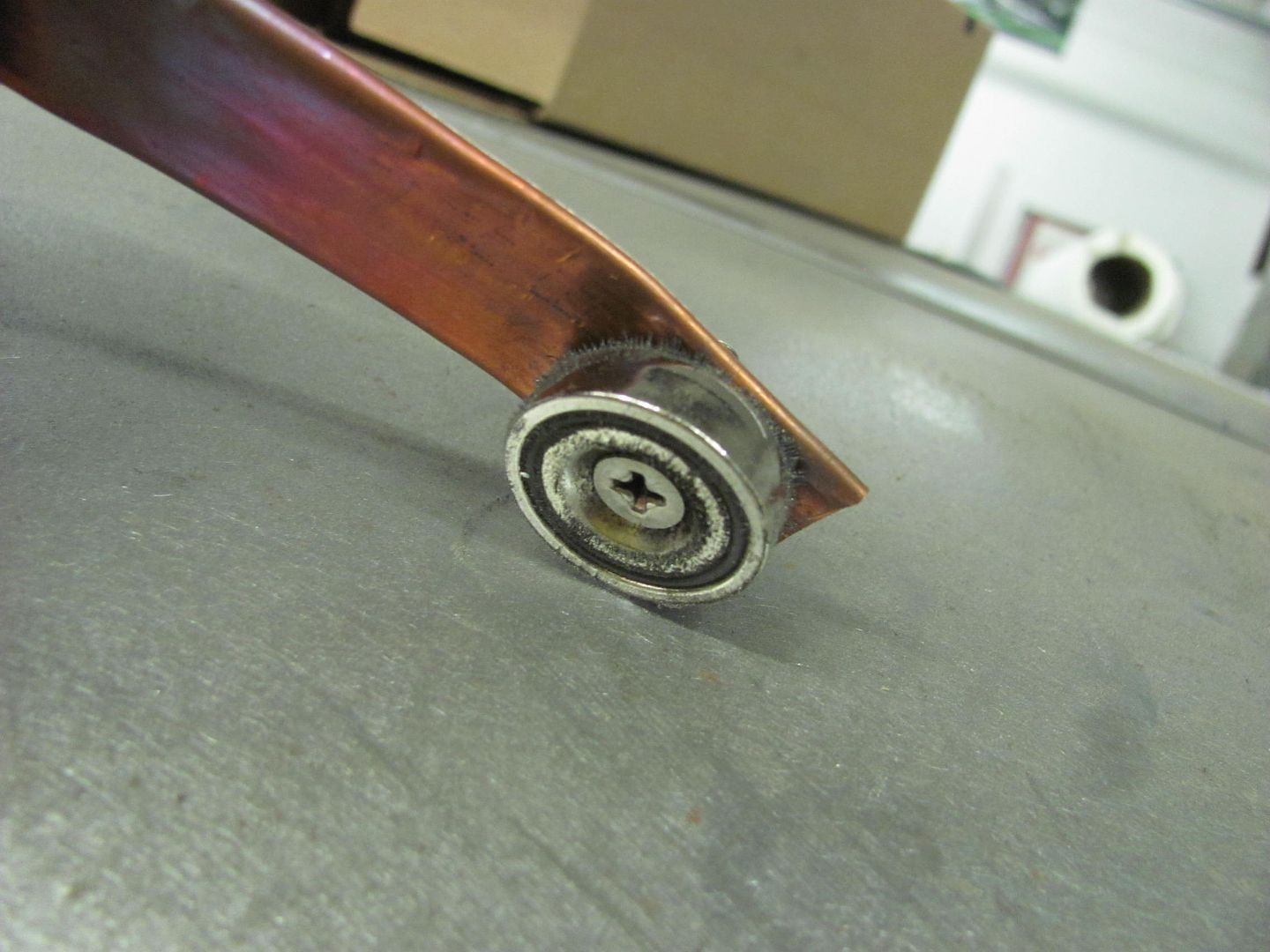 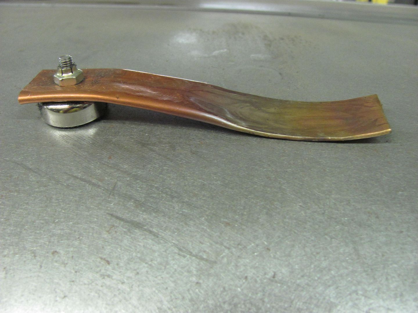 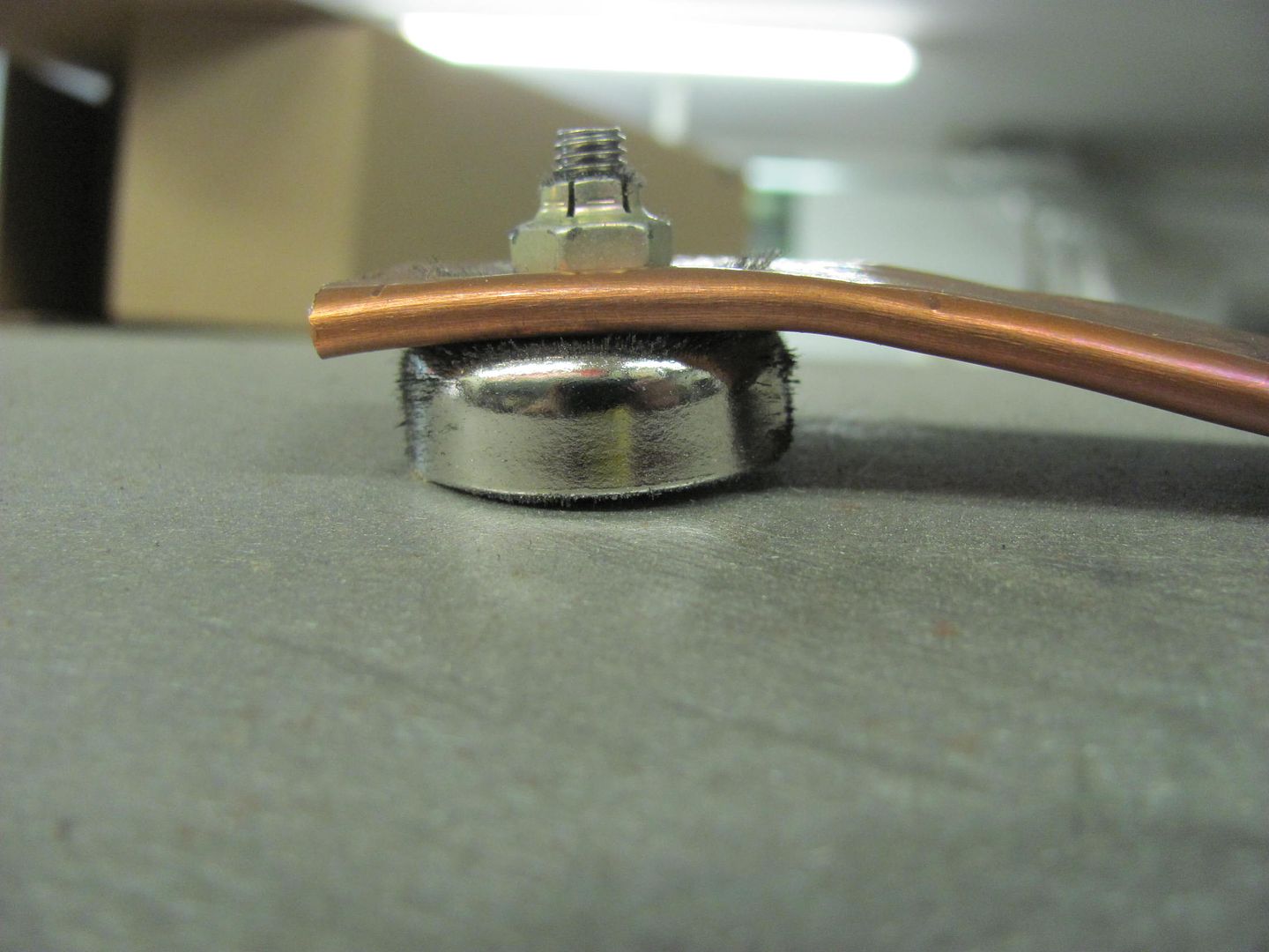 Each use will tend to leave the copper soot covered, so I used a welding brush to clean the copper between each weld. 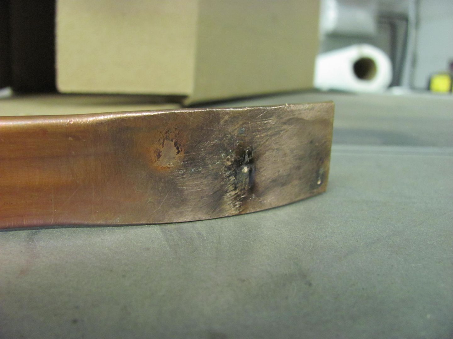
__________________
Robert Instagram @ mccartney_paint_and_custom McCartney Paint and Custom YouTube channel Last edited by MP&C; 10-09-2014 at 09:02 AM.
|
|
#25
10-09-2014, 01:48 PM
|
|||
|
|||
|
Marcus - Thanks for the sharing your chassis building experience( h-press and boxing). I have pondered similar builds but chassis seems to present unique challenges. Going forward, there will less and less old chassis (whatever is plural for more than one chassis) to use and most will need some repair. Can't wait to you start carving up the sheet metal.
 Tim
__________________
Tim Millward
|
|
#26
10-09-2014, 09:36 PM
|
|||
|
|||
|
Subscribed, for sure. Thanks for taking the time to post, and all the details, like the way you bent the frame rails in either plane.
You mentioned the "Government Street Rod Manual". Is that something I can find online? I would be very interested in a link.
__________________
Mark from Illinois
|
|
#27
10-09-2014, 11:47 PM
|
||||
|
||||
|
Quote:
http://www.infrastructure.gov.au/roa...treet_rod.aspx
__________________
Marcus aka. Gojeep Victoria, Australia http://willyshotrod.com Invention is a combination of brains and materials. The more brains you use, the less materials you need.
|
|
#28
10-09-2014, 11:54 PM
|
||||
|
||||
|
Thanks for showing interest and can include more details that I was going to leave out.
On the copper, I didn't think you could use rare earth magnets as effects the arc? I have seen that with tig work on Welding tip and tricks, but don't know about mig?
__________________
Marcus aka. Gojeep Victoria, Australia http://willyshotrod.com Invention is a combination of brains and materials. The more brains you use, the less materials you need.
|
|
#29
10-09-2014, 11:57 PM
|
||||
|
||||
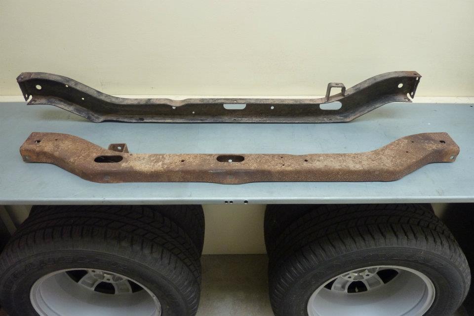 Need a cross member to go between the frame rails where the coil mounts are to stop them twisting. Decided to make one out of two originals rather than just a piece of tubing. Rather than run them stock like shown, will flip them upside down so they can support the floor of the bed as well. 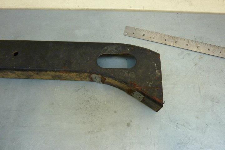 Have cut them down to length and will shorten the ends up to match the rail height. Can just see what I will cut out. 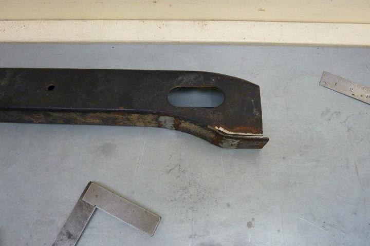 Bent to the new shape keeping the curve smooth to flow better with the rest of the cross member. 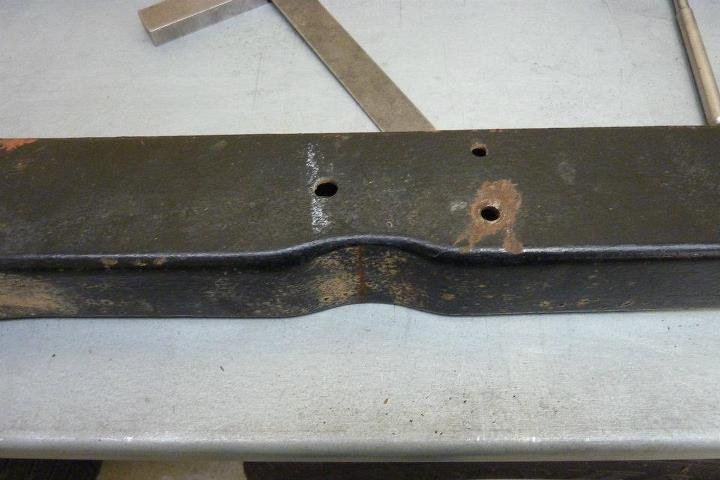 Need to remove this indentation as wont match up once both cross members are welded together back to back. 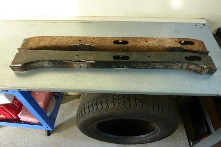 I cut up the middle of the indentation and then out to the sides in a T shape. Then hammered the flange flat ready to weld it. The semi-circular hole was just filled with weld by placing copper behind it to stop the weld falling through. 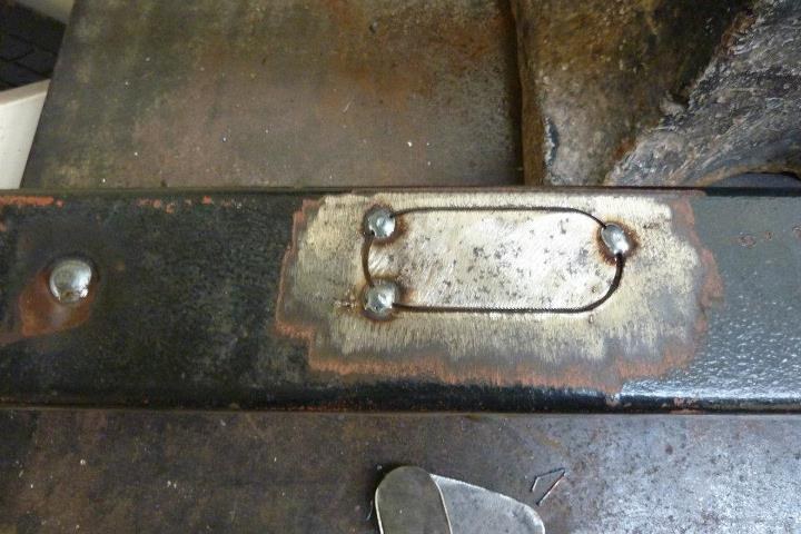 Cut fill patches from the ends which were cut off the same cross members. 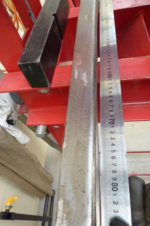 The cross member already had some bend in it and got worse after welding the patches in 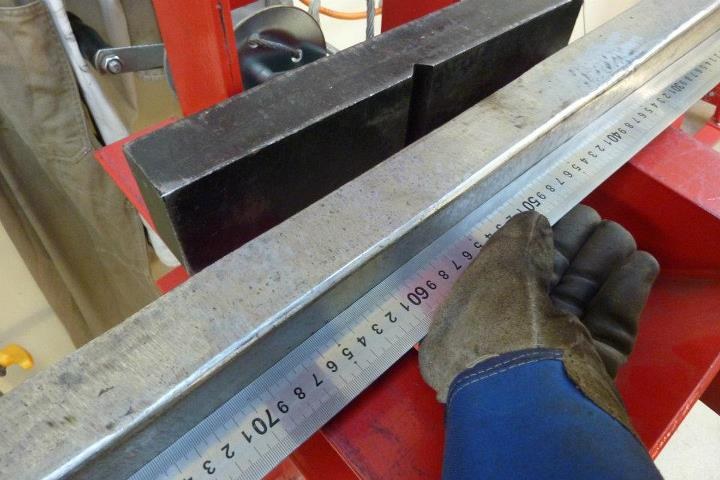 Placed it in the press and went from one end to the other using only about 1 ton of pressure and it brought it out nice and straight. 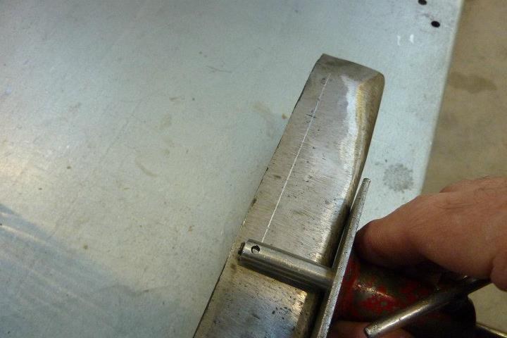 Just trimming the width of the cross members the same amount to get the overall width I was after. Using a back-gauge so that even if the cross members are not perfectly straight, it can be made so as the two halves are tacked together. 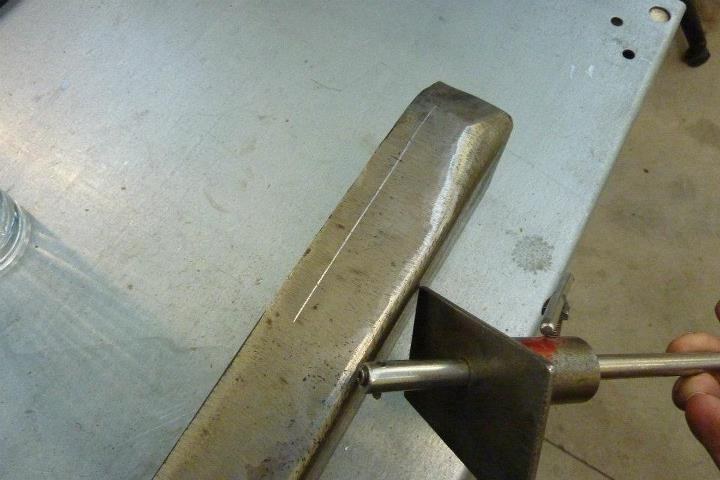 I made this back-gauge about 30 years ago from some scrap lying around. The bit that makes the mark is just a piece of broken drill bit held in place with a set screw. 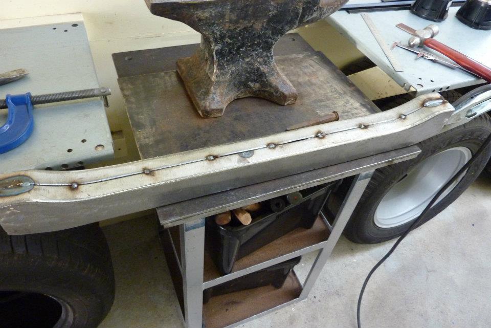 All tacked together with the joint bevelled and a small gap left for full penetration 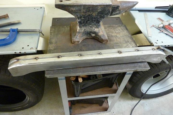 Also hammered the flange up slightly so it would pull square once welded. 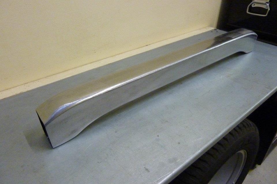 Think this looks better than just a piece of square tubing. Also prefer to use as much as possible from the old chassis's so nothing goes to waste. Also makes registration easier here. 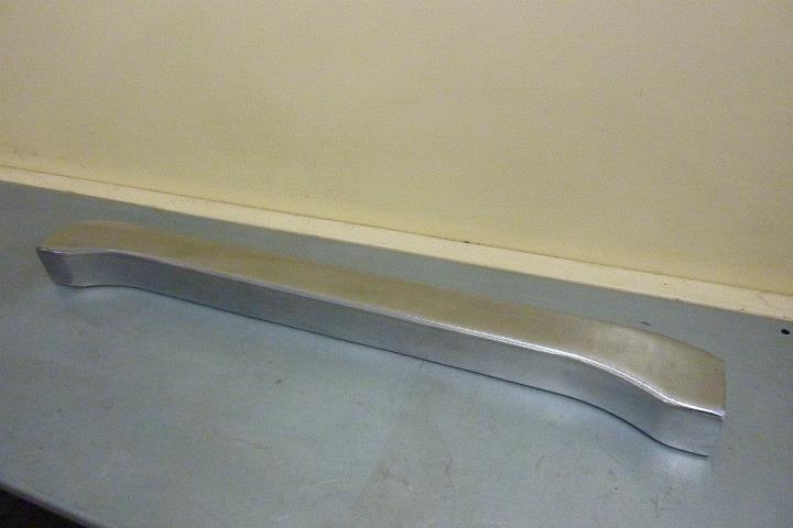 The rise in the middle will give extra diff clearance at full compression too.
__________________
Marcus aka. Gojeep Victoria, Australia http://willyshotrod.com Invention is a combination of brains and materials. The more brains you use, the less materials you need. Last edited by Gojeep; 08-01-2017 at 03:03 AM.
|
|
#30
10-10-2014, 12:00 AM
|
||||
|
||||
|
Haven't been able to touch the project in over a month, but got a bit of time this week when I was waiting for a part for something else I am working on.
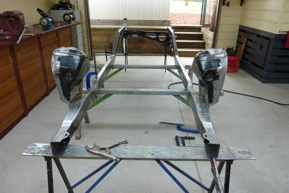 So starting putting the frame together. First made some trestles with bits of scrap I had. The tops of the main ones were used previously as the braces between the rails when I fully welded in the boxing plates. 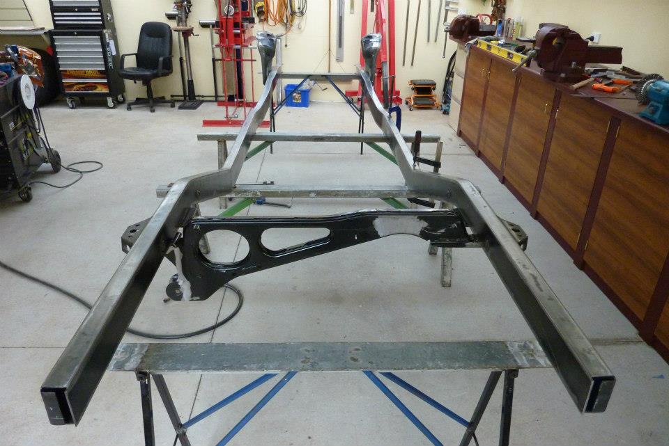 The frame was made perfectly level left to right and front to rear on the straight sections both at the rear and under the cab. Also across the top of the front suspension uprights and under the frame where the engine cradle bolts up as well. 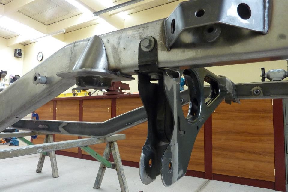 Was good to see that the threaded inserts for the panhard rod mount all lined up perfectly. Can see the coil mounts in position ready to be fully welded too. 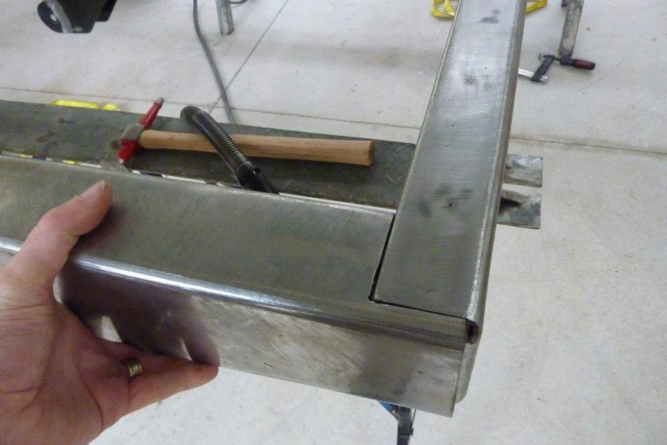 The rear cross member looks to be a good fit. Will have to bevel the joins to get full penetration of the welds. 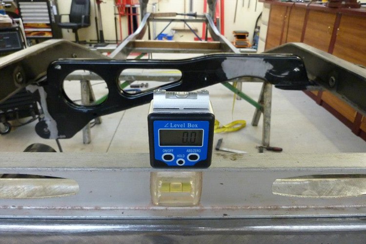 Using a digital angle gauge to make things more accurate. It did show up that I had a twist in one of the rails in the front section. Looks like the bracing I had between the rails where it was straight worked perfectly, but needed more in the front section. A cross brace would have helped there. 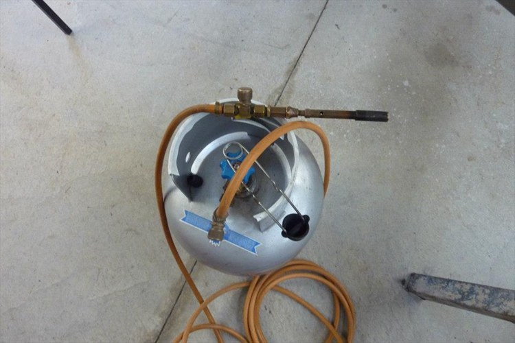 Just using a propane torch to get the twist out of one frame rail. Advantage of using this is the maximum heat it can get up to is perfect for heat straightening without loosing tensile strength that you can get for going too hot. 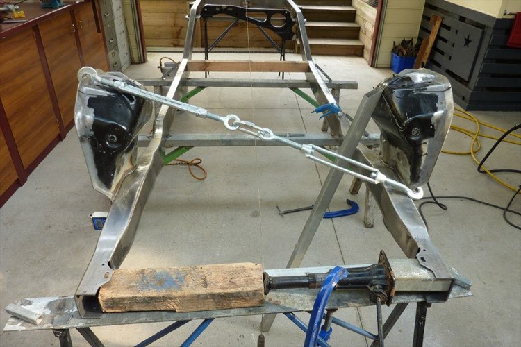 To assist getting the twist out of the left rail in the picture, I have used a couple of turn buckles. Also notice that the other side I don't want effected has been braced onto the ground. 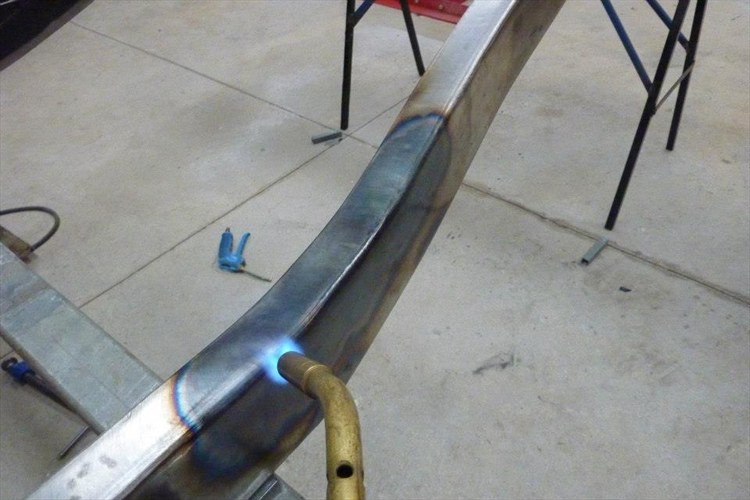 I heated along the the outside corner and the lower opposite inside corner to twist the frame inwards. It was 2.4 degrees out in total before I started and 0.1 degrees by the time I finished.
__________________
Marcus aka. Gojeep Victoria, Australia http://willyshotrod.com Invention is a combination of brains and materials. The more brains you use, the less materials you need. Last edited by Gojeep; 08-01-2017 at 03:08 AM.
|
 |
| Thread Tools | Search this Thread |
| Display Modes | |
|
|


 Linear Mode

