
|
|
|
#761
 10-01-2017, 05:00 AM
|
|||
|
|||
|
Marcus, Great post on problem solving the window channel and handle operation, Well executed and the fitment of the latches is 1st class.
I'm not a fan of the bear claw as they are pretty much impossible to get open when they fail, and adjustment is limited during service. I'm not sure of the brand you have but the earlier styles of the bear claw were a ripe bugger. I have to say this, Not coming from a professional shop, this is one of the most informative, professional and A class workmanship posts that I have ever come across. Well done Marcus.   PS On those Latches, maybe it was the way they were fitted.
__________________
John EK Holden V8 Last edited by Oldnek; 10-01-2017 at 05:02 AM. 
|
|
#762
10-01-2017, 06:35 AM
|
||||
|
||||
|
Excellent solution.
Thanks for showing it.
|
|
#763
10-02-2017, 02:30 AM
|
||||
|
||||
|
Quote:
Quote:
__________________
Marcus aka. Gojeep Victoria, Australia http://willyshotrod.com Invention is a combination of brains and materials. The more brains you use, the less materials you need.
|
|
#764
10-08-2017, 03:23 AM
|
||||
|
||||
|
Sorry about going into so much detail on these locks, but I struggled to find much about this on the net so thought others might need the information one day.
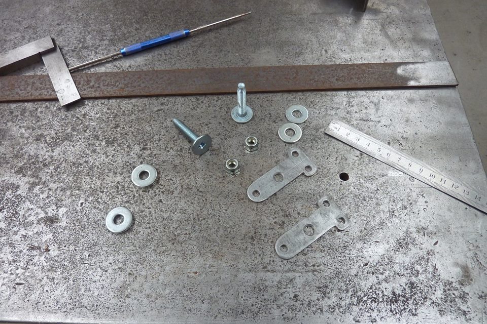 Next up is making the doors lock and unlock. I wanted a manual release on the inside of the door in case something happened to the central locking. I had these wide flat head bolts to use as pivots from an old CRT monitor I think. I always strip down and take fasteners out of everything that is to be thrown out and everything goes into the sorted bins I have. The pivot links were cut from some flat stock. 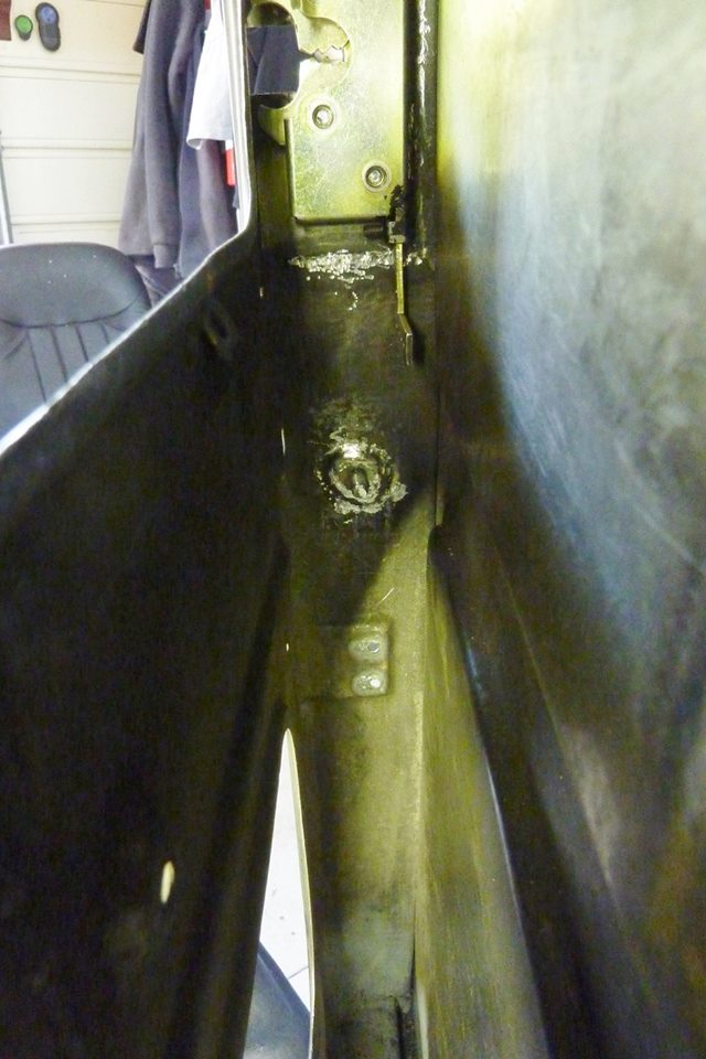 I fully welded the head of the bolt to the door frame. I didn't want any long term fatigue so why I chose the widest flat bolt/screw head to use. What needs to be operated is the L shaped lever coming out of the lock and needs to go straight up and down, but is on the wrong side of the glass. 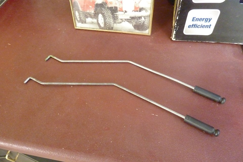 I used these door lock release rods from the donor front doors and bent them to suit the offset I needed. 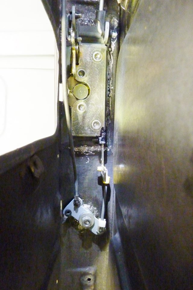 This is the best way I could think of to move the lever up and down directly under it. It sometimes would jam if you tried pushing up on an angle. This is another reason I ran the latch with the locking lever at the bottom as it would work conventionally. Pulling up on the door release knob would pull down the lever and unlock it like shown. 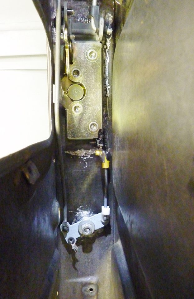 Pushing down on the inside lock rod would push it into the locked position. The pivot link was made as long as I could to get enough travel without binding. Also made sure the pivot link is level halfway through its travel to prevent binding as well. A nyloc nut on the pivot bolt will used for final assembly. 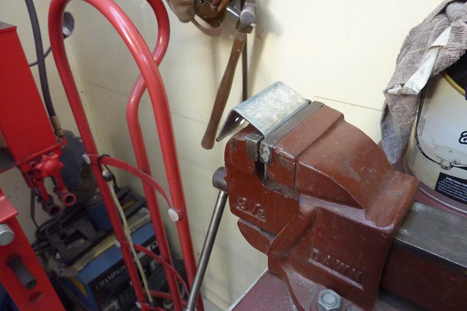 Next thing was to make a mount for the central locking actuator/solenoid. I didn't want another set of screws or rivets at the end of the door, or on the inside either. So will hide them under the door card. The metal was too thick for my folder so knocked it over in my smallest vise. 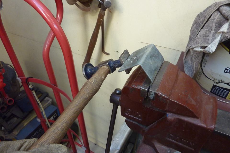 Needed a joggle in it to suit the door. So after the first fold was made, I raised it up 1/4" and then bent it back the other way. Held this hammer against the edge to start with and hit it with a nylon mallet. 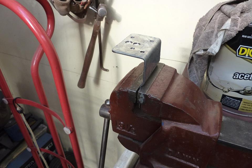 One joggle! 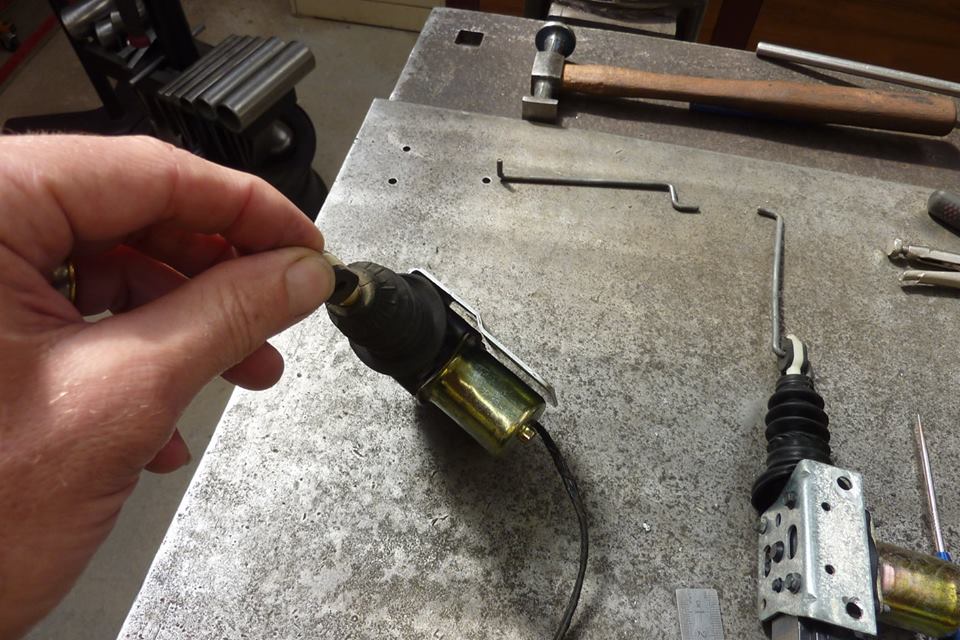 It clears the motor nicely. These came out of a XJ Jeep Cherokee, pre 97, but are the same found on many GM cars from the 80's and early 90's. They actually have a rack and pinion system in them. Better than the cheap Chinese versions in the kits. 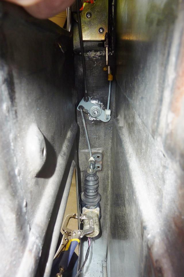 The stock rod for the actuator won't work as angle is too great and in the way of the end of the glass channel. 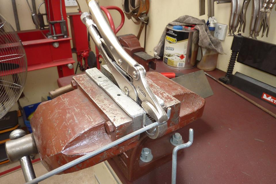 Bent the first bend in the vise but the second bend won't work in it. So clamped a set of Visegrips in the vise to make the second bend. 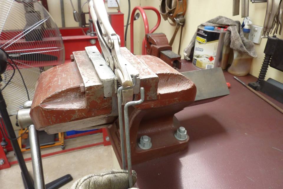 Knocked it over and now matches the stock rod. 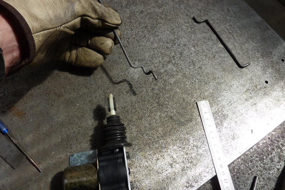 I also put another step in it so it would line up directly under the pivot link. Less wear on the actuator this way. 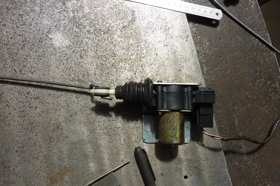 First two bends are to locate it in the top of the actuator. 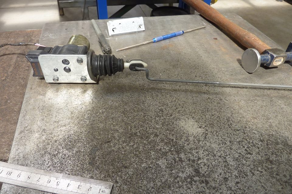 Last two bends are to get it lined under the pivot link. 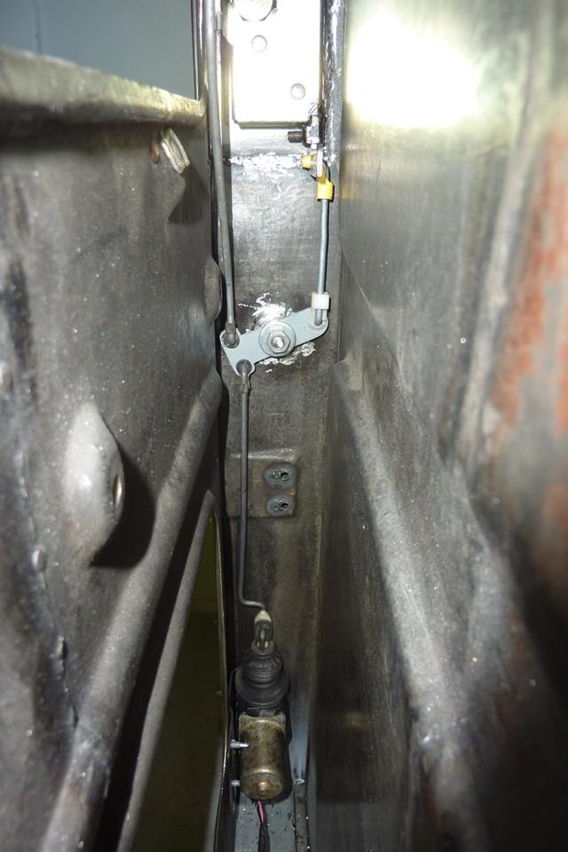 Here it is all mounted up. In the locked position now. 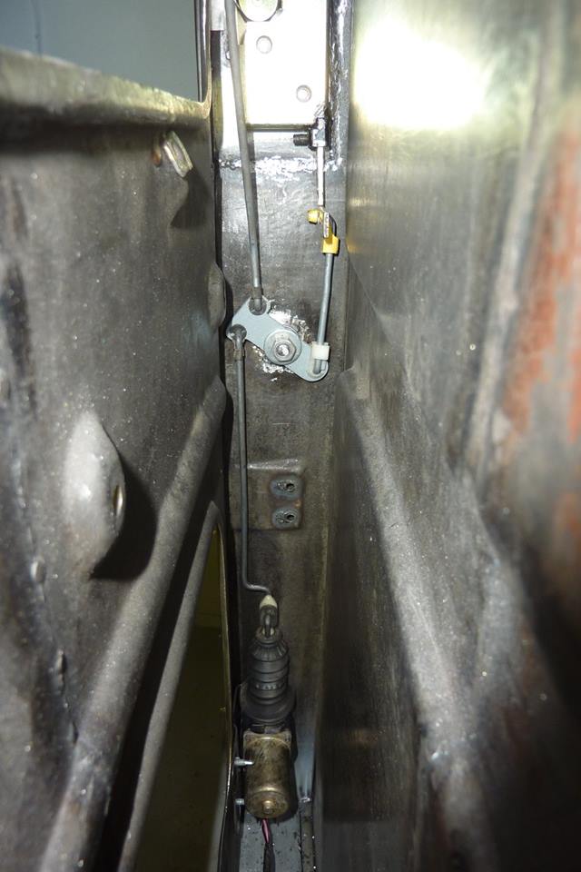 Unlocked position. 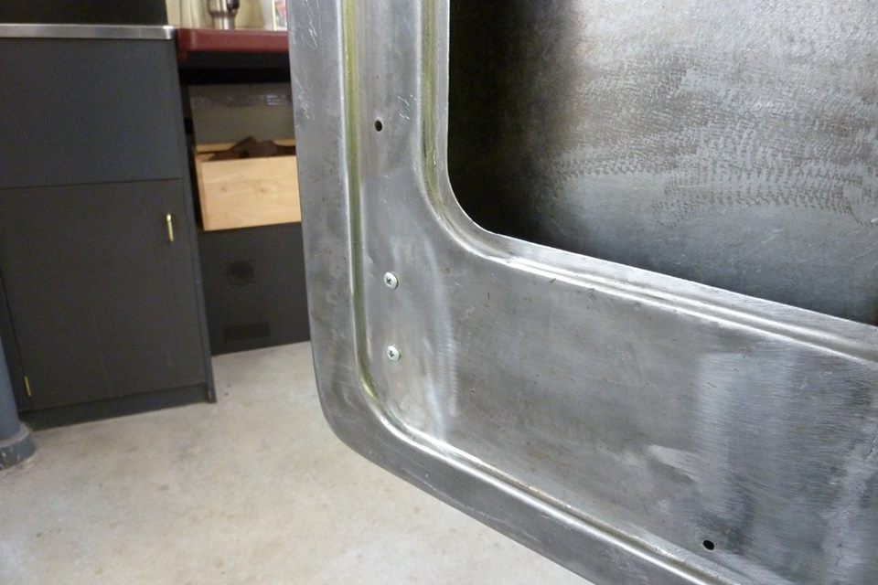 Screws will be hidden under the door card which sits inside the recess. Wafer head self drilling screws were used to hold it in place. The self drilling ones are hardened and won't wallow out over time. Can also see why the joggle was needed in the bracket.
__________________
Marcus aka. Gojeep Victoria, Australia http://willyshotrod.com Invention is a combination of brains and materials. The more brains you use, the less materials you need.
|
|
#766
10-08-2017, 05:06 PM
|
|||
|
|||
|
Top work Marcus and a brilliant tutorial!

__________________
Why does dust stick to everything, but nothing sticks to dust?
|
|
#767
10-09-2017, 04:38 AM
|
||||
|
||||
|
Glad it has been a help Charlie and Leif.
__________________
Marcus aka. Gojeep Victoria, Australia http://willyshotrod.com Invention is a combination of brains and materials. The more brains you use, the less materials you need.
|
|
#768
10-13-2017, 10:00 AM
|
||||
|
||||
|
Marcus: for the locks on the C5GTO, I didn't want the extra weight of power silenoids, etc, so the solution I came up with was to use the throttle levers/cables from a lawn mower. My solution looks down right primitive compared to yours
__________________
Joel Heinke Be original; don't be afraid of being bold!
|
|
#769
10-14-2017, 06:02 AM
|
||||
|
||||
|
Quote:
__________________
Marcus aka. Gojeep Victoria, Australia http://willyshotrod.com Invention is a combination of brains and materials. The more brains you use, the less materials you need.
|
|
#770
10-15-2017, 03:08 AM
|
||||
|
||||
|
Little by little I'm getting there.
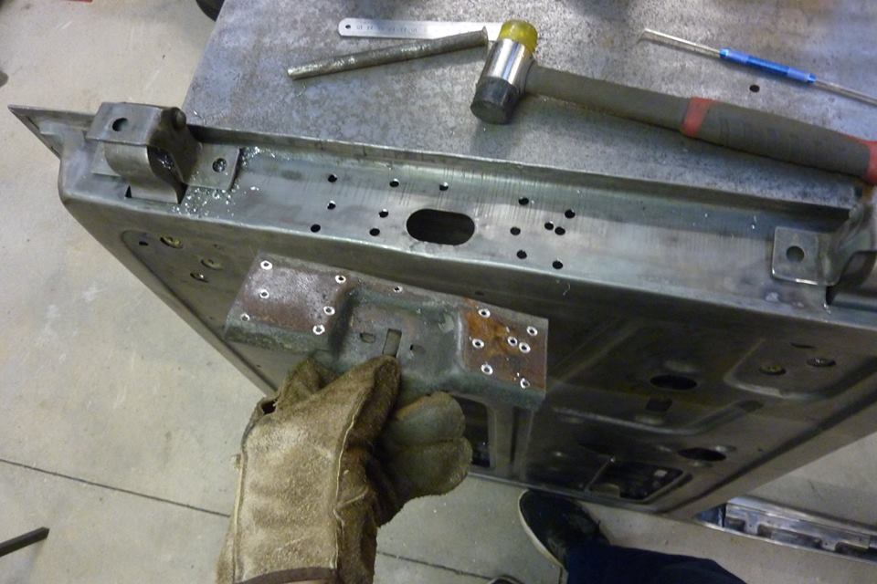 I am getting rid of the 1/4 vent windows and going to one piece glass. It means that the door check bracket has to be removed as can't run that style anymore. I'll have to come up with something else like a simple strap that the CJ Jeeps have. 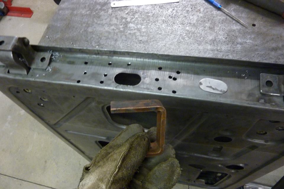 To fill all the spot weld holes I just use a thick piece of copper under the hole and weld it shut with the mig. The oval hole I have cut a patch for. 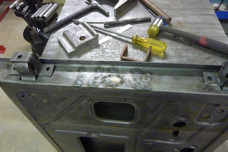 All the holes gone. Will grind them down to a razor blade thickness above the parent metal. Then flap disc to flush followed by a strip disc. 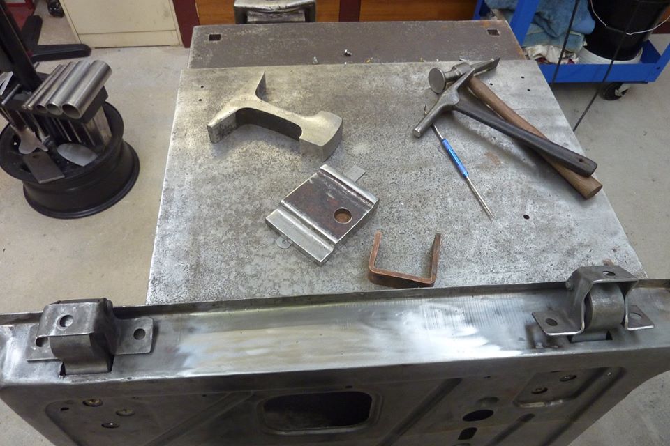 Hammer dollied the weld area flat and all done. 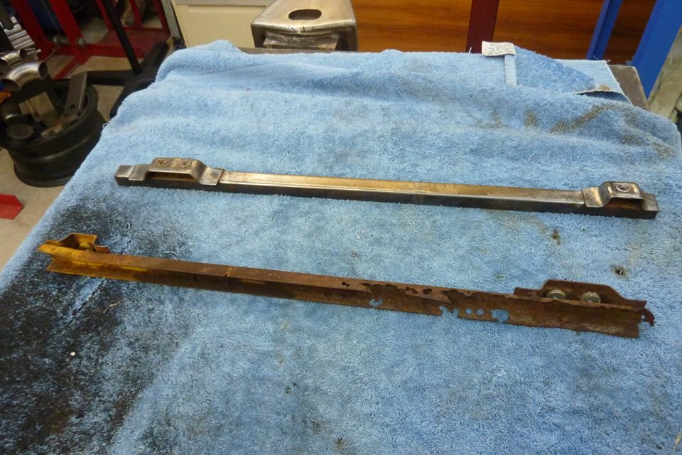 Out of the four doors I had, only one of the window channels needs replacing. I'll be using the same channels that ran down the latch end of the doors at both ends now. They are left and right so need one of each in each door. 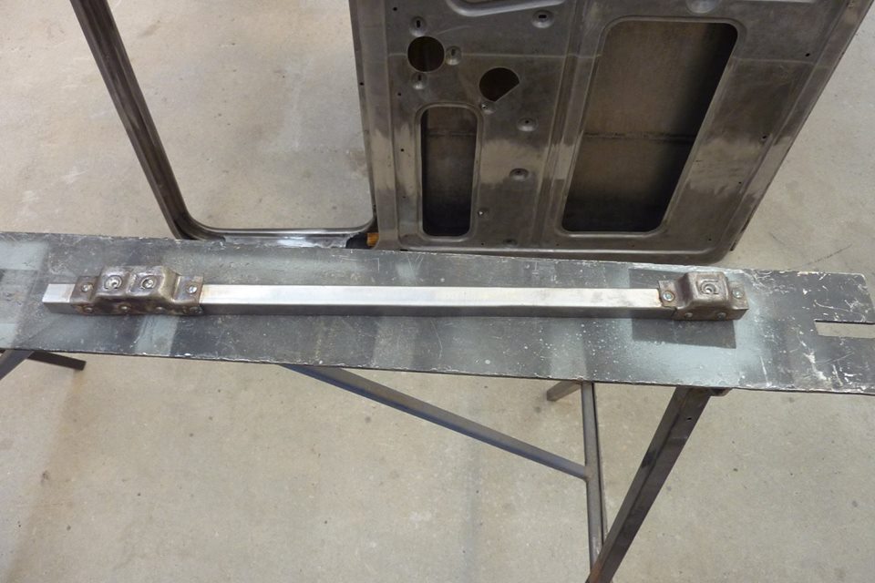 Fortunately I only had to fold up the channel and the mounts were still alright. 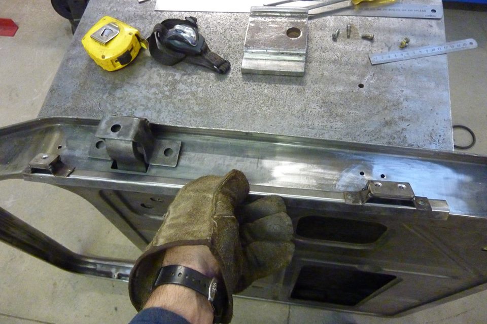 The channel will sit inside the door where shown by the holes drilled. It will sit at the same height as the latch end of the door. Also note that 5mm-3/16" spacer was added to the mounts to space it out to line up under the window frame correctly and not interfere with the hinge reinforcements.  Just showing on a scrap door the curved piece in the corner, as well as the piece holding the inner and outsides together, that has to be removed. 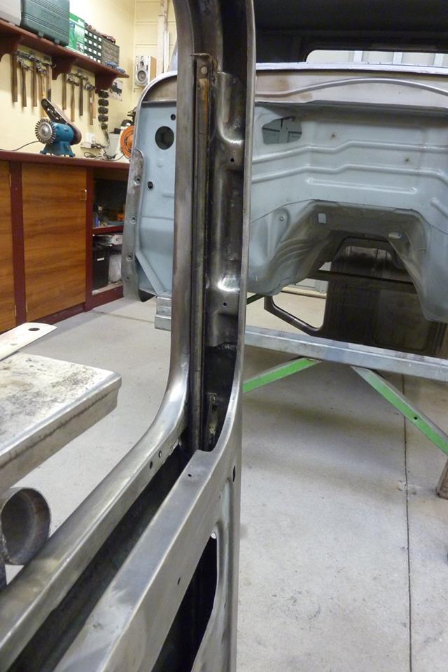 The latch end of the door channel alignment was first checked to make sure it was a straight line from the window frame down all the way inside the door channel. Used the old 1/4 vent channel inside the other one to check, but also found a string line worked well. Glass does not bend so needs to be inline. The factory holes were a bit off so I welded them shut and moved them over and then copied that over to the hinge side of the door. 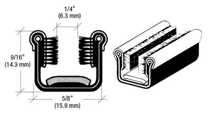 I bought two 2400mm-96" lengths of flexible window channel the same as stock. They are cloth covered with the bristles on the sides. 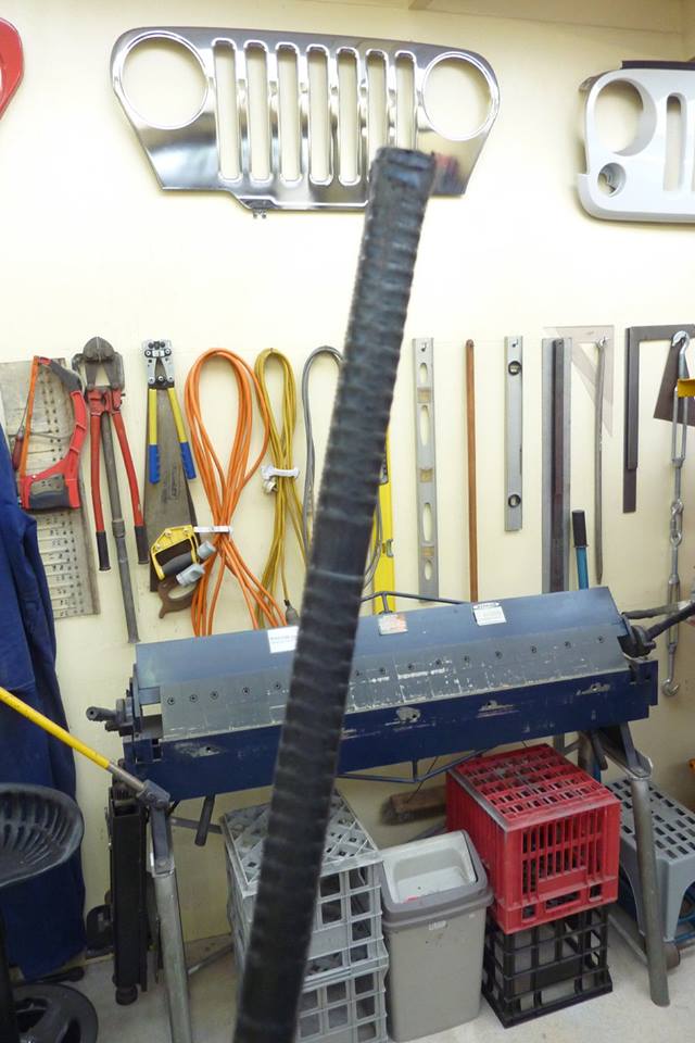 Can see the back of the channel is segmented allowing you to bend it around the corners.  The channel inside is made from aluminium. 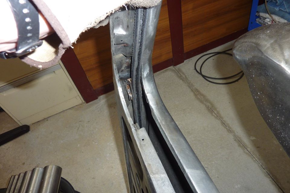 Can see how it will come up out of the new position at the front of the door. 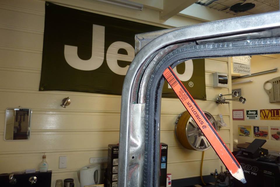 To help it bend around the corners I found a carpenter's pencil worked well. I secured the channel the same as stock with some small counter sink screws. 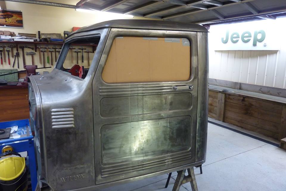 I cut some cardboard roughly into shape and then marked around the inside edge of the window channel. The added the depth of the channel, 10mm-3/8", to that mark with some dividers. 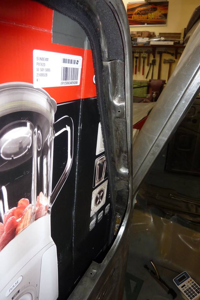 Can see how it sits inside the channel. I made it go inside the door to add some stability to the front edge when down.  The bottom of the template is level with the top of the door card recess. 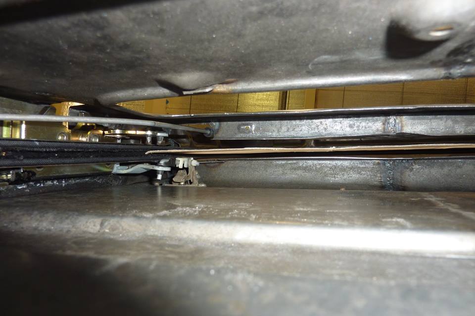 I was happy to see that it cleared the door handle linkages. I will make templates from MDF next using the cardboard one to scribe around.
__________________
Marcus aka. Gojeep Victoria, Australia http://willyshotrod.com Invention is a combination of brains and materials. The more brains you use, the less materials you need.
|
 |
| Thread Tools | Search this Thread |
| Display Modes | |
|
|


 Linear Mode

