
|
|
|
#41
 10-13-2014, 12:09 PM
|
|||
|
|||
|
Brilliant.
I'm learning a ton of stuff, up in heah.
__________________
Bruce 
|
|
#42
10-13-2014, 05:44 PM
|
||||
|
||||
|
Quote:

__________________
Marcus aka. Gojeep Victoria, Australia http://willyshotrod.com Invention is a combination of brains and materials. The more brains you use, the less materials you need.
|
|
#43
10-13-2014, 06:11 PM
|
||||
|
||||
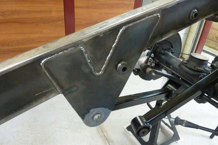 I was not happy with the original design of the end of the tube being smaller than the side of the bush that rests against it. So I cut a disc out of some 4mm plate to weld onto the end of it the same size as the side of the bush. 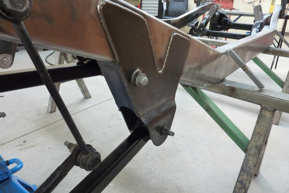 To further strengthen the mounting plates I welded in a filler piece to box the ends of it which will also keep the sides nice and straight. 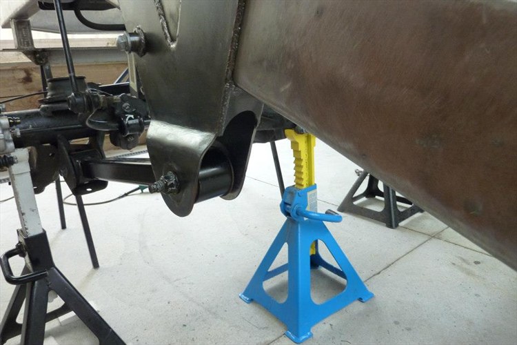 Plated the front face even though fairly small. 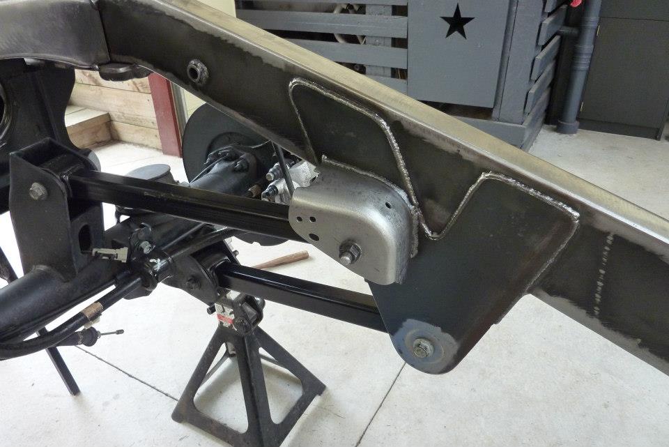 The original modified support bracket was also welded in to support the other side of the upper mount. You also have to forgive the appearance of my welds on these upper and lower mounts as the mig kept cutting out multiple times on me while in the middle of a weld. Some times would not start at all. Stripped down the gun and found a loose wire that needed to be re-crimped. 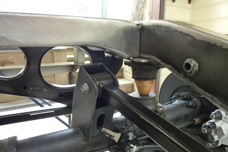 With the arms all now fully in place, I fitted the bump stops so I could check the clearance of the upper arm bracket to make sure it wouldn't hit the cross member. There was still 1.5" of clearance at full travel so that allows enough for the bump stop compression in a hard hit. 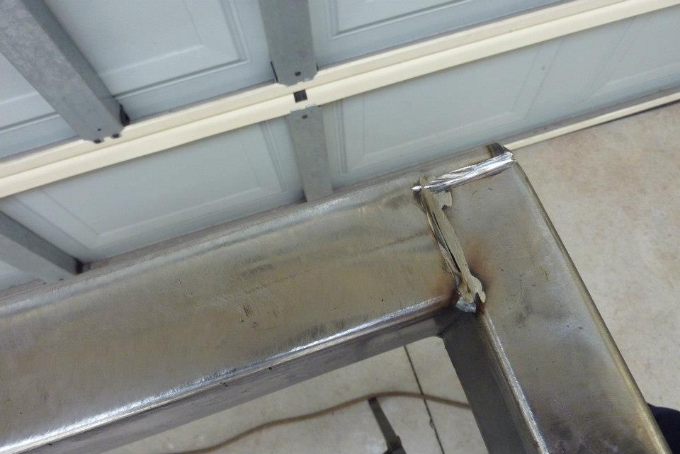 Decided to weld in the rear most cross member. First ground a deep V so I would get full penetration 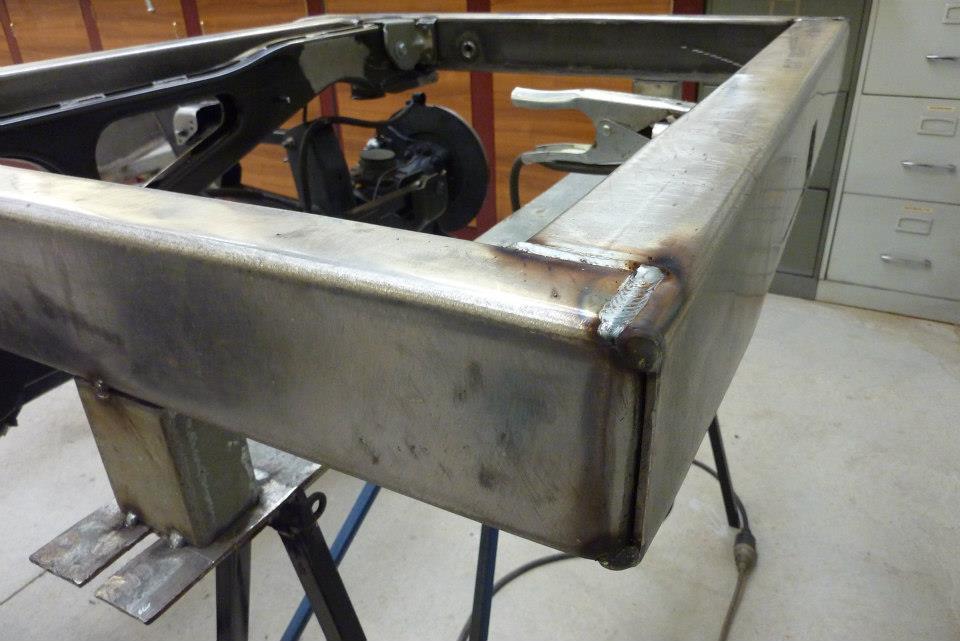 Then laid down the welds. The outside one doesn't require any further preparation. 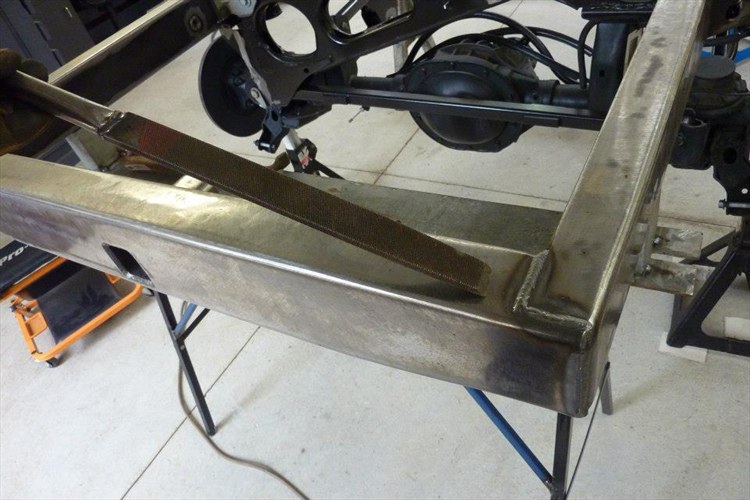 To clean up any spatter after welding. I first just run over it with a wire brush. Then use this old blunt file that I sharpened the end of to knock any splatter off. Any that doesn't come off easily with this I will then use a hammer and cold chisel. 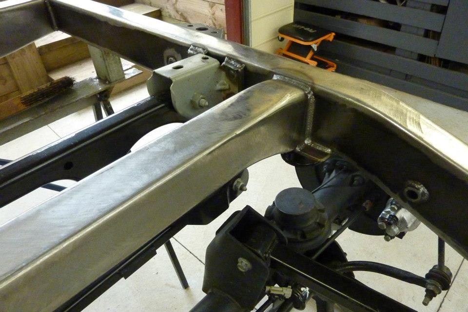 Now that I know that I have enough clearance under the cross member, could finally weld it in fully. Was nice to have the mig running better after the repair now too. 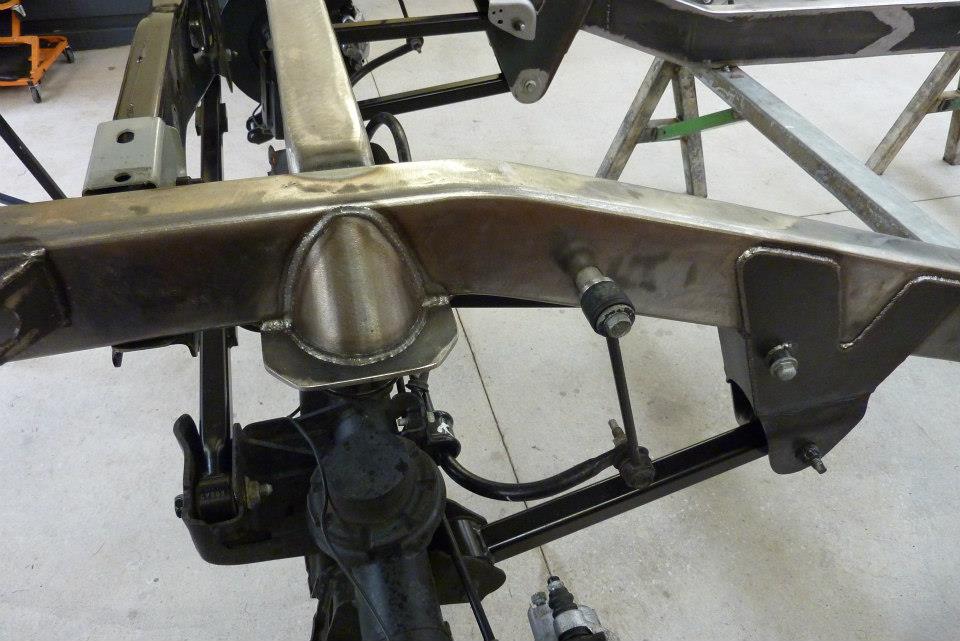 Also had left the coil support until this time so I could balance the welding by swapping sides between this and the cross member. 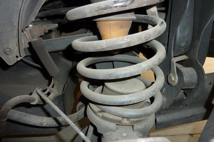 Something that has always bothered me was the angle of the lower coil mount on the rear axle. Here is a photo I took of it before strip down. Remember the rear was not effected at all when the Harley rider hit the front door and wheel, so was this way from the factory. 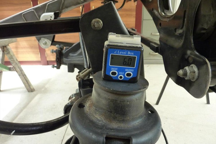 I found the coil bucket was sitting at 6* at ride height. The other side was at 5*! Was too much to leave as is and have no idea why the factory did it this way. Even at full compression it still was not level. 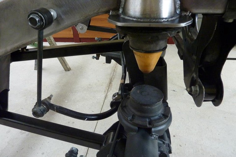 So I ground off the welds and and reset it at the best angle between ride height and full compression. 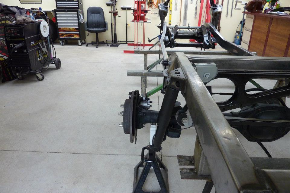 Threw the rear shocks in too. Can now see why the upper mount was made at a 8* angle. 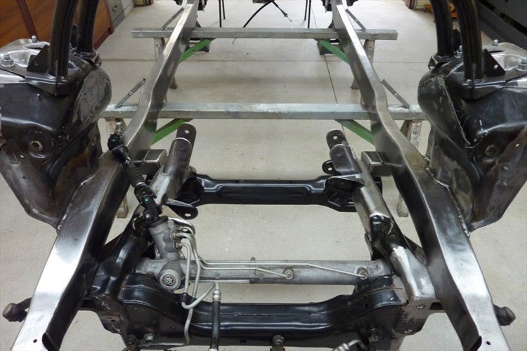 Steering rack bolted into the stock location. 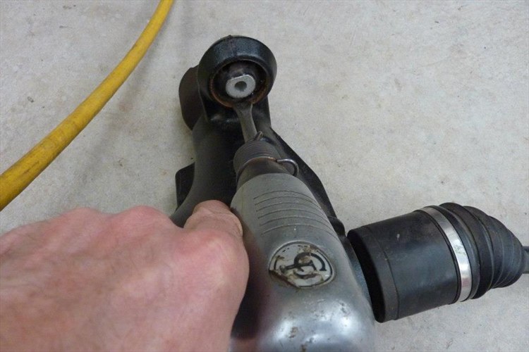 Wanted to fit the front diff too, but two of the bushes had a tear in them from the accident. Fortunately had already got the replacement bushes last year for it. Just rattled the old one out using a air chisel pushing against the outer steel sleeve. Taking care not to score the housing. 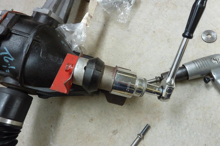 Left the new bush in overnight in the freezer to make fitting it easier. Just make sure the bush is orientated the right way as they allow more movement in one direction than the other. The slot in the centre sleeve needs to be at the top or bottom as you can see in the first shot. 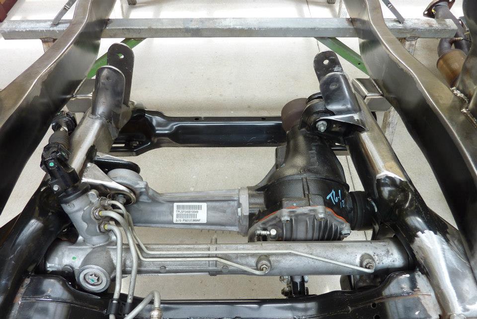 Front diff is now mounted into place. Can also see how much I have moved the engine mounts back as originally the left one in the picture was over the top of the diff mount.
__________________
Marcus aka. Gojeep Victoria, Australia http://willyshotrod.com Invention is a combination of brains and materials. The more brains you use, the less materials you need. Last edited by Gojeep; 08-01-2017 at 03:29 AM.
|
|
#44
10-14-2014, 08:48 AM
|
||||
|
||||
|
Hi Marcus
You are really doing a wonderful build! Thanks for taking the time to share with the members, I know it is very time consuming, but really appreciated. Does the axle housing need to be straightened after rebuilding the mounts after changing their angle? Steve
__________________
Steve Hamilton Hamilton Classics Auto Restoration & Metalshaping Last edited by route56wingnut; 10-14-2014 at 08:55 AM.
|
|
#45
10-14-2014, 06:45 PM
|
||||
|
||||
|
Quote:
The axle didn't need any straightening as each weld was only very short and spread around. Made sure they were cooled straight away and cold before starting the next one opposite it to keep it even.
__________________
Marcus aka. Gojeep Victoria, Australia http://willyshotrod.com Invention is a combination of brains and materials. The more brains you use, the less materials you need.
|
|
#46
10-14-2014, 06:46 PM
|
||||
|
||||
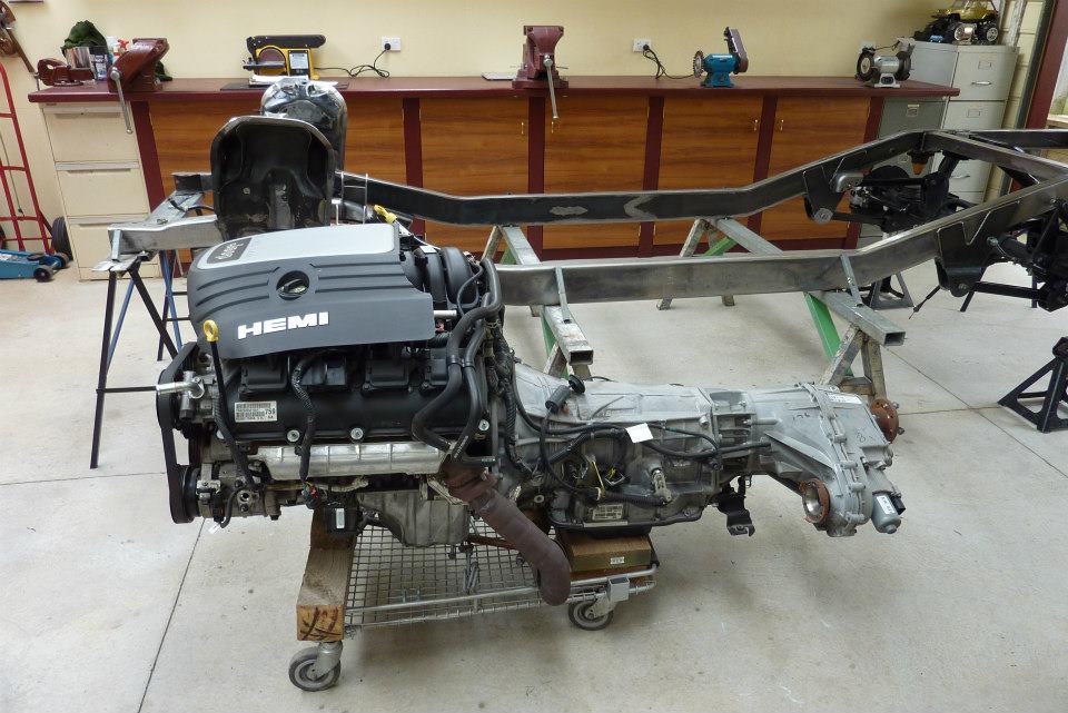 This was an exciting time for me. Wheeled the engine/transmission/transfercase assembly across ready to be lifted in! 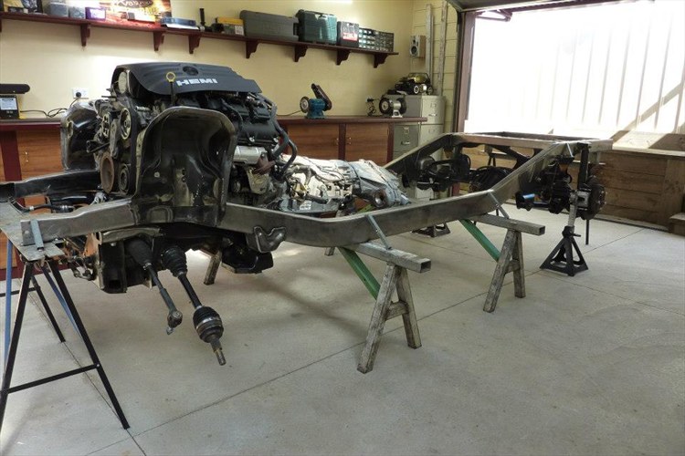 Overall shot of the frame and drivetrain in place. 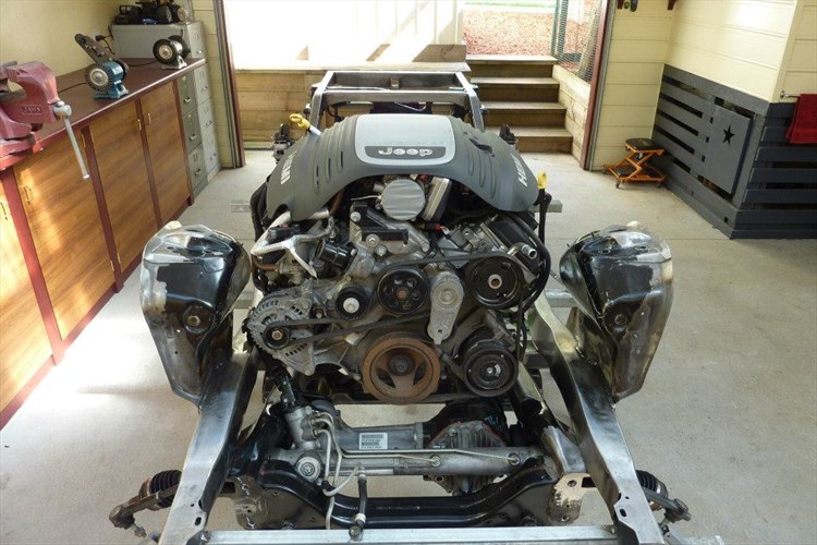 ] ] 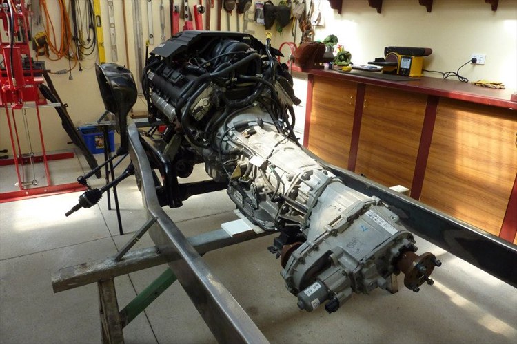 Got a bit carried away with the engine in shots. 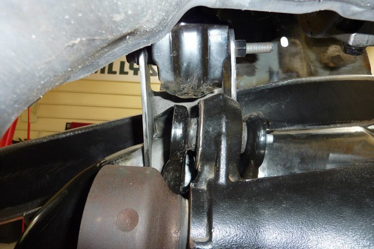 One of the reasons I added the front diff assembly and the steering rack was to make sure I had enough clearances. Has been 1.5 years since making the engine mounts so good to double check everything under the installed weight. Everything checked out well except for the clearance between the diff mount and the engine mount. I had made it with 3/8"-10mm of clearance, but the engine mount compressed 1/4"-6mm once underweight. 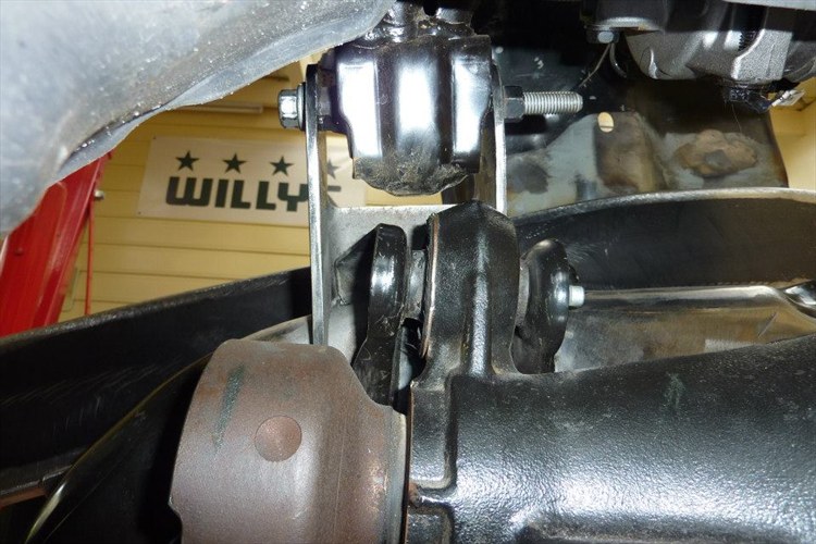 It probably would have been alright as the engine torque would lift the engine up on this side giving more room. But I couldn't be 100% sure so simply welded up the bracket holes and re-drilled them 1/4"-6mm higher. Now I am confident it will be fine. 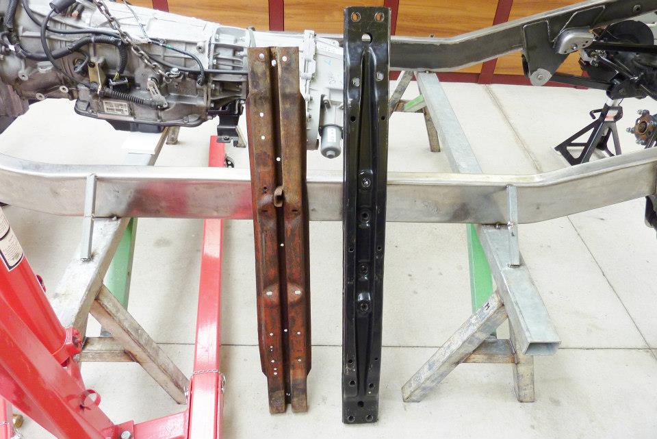 Funny how the two cross members look remarkably similar even though there is 60 years between them. You are looking though at the top of the original and the bottom of the new one though. 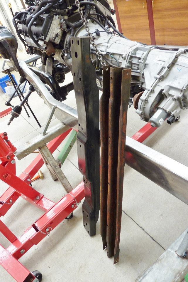 Was thinking of using the old one at first but worried it might not be up to holding the weight of the new drive train. 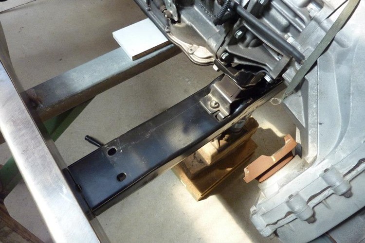 The frame depth in this section is 2" deeper than on the donor Jeep. So I had to shorten the cross member so it would fit between the rails. 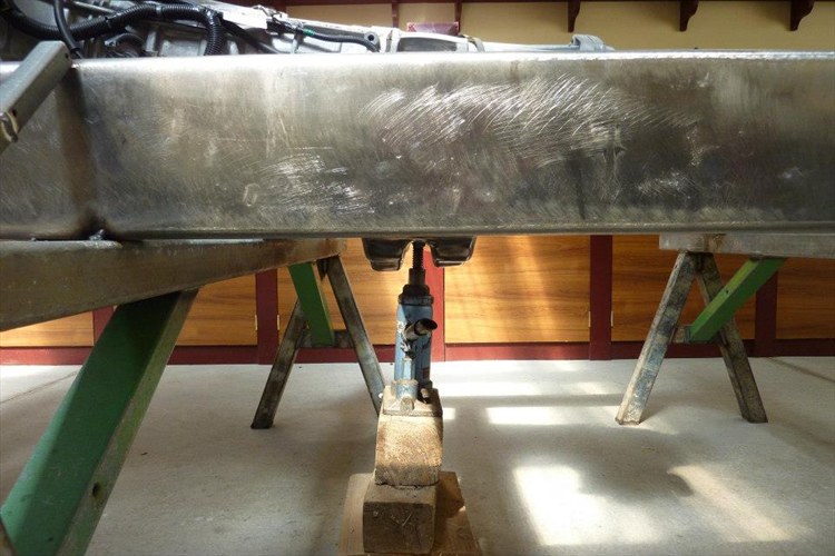 Good thing is that there is an 1" of clearance under the auto's sump compared to the bottom of the frame rail. Even the transfercase sits higher than the bottom of the frame. 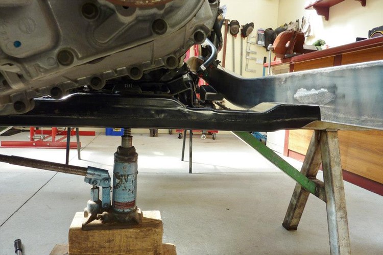 It worked out the end of the cross member sits flush with the bottom of the rail once the stock drive line angle was set. Will have to make some now mounts for it next.
__________________
Marcus aka. Gojeep Victoria, Australia http://willyshotrod.com Invention is a combination of brains and materials. The more brains you use, the less materials you need. Last edited by Gojeep; 08-01-2017 at 03:33 AM.
|
|
#48
10-15-2014, 03:12 AM
|
||||
|
||||
|
Quote:

__________________
Marcus aka. Gojeep Victoria, Australia http://willyshotrod.com Invention is a combination of brains and materials. The more brains you use, the less materials you need.
|
|
#49
10-15-2014, 10:41 AM
|
||||
|
||||
|
ok Marcus what a great build but your work shop is just way too neat :-)
__________________
David Geelong victoria Australia
|
|
#50
10-15-2014, 06:33 PM
|
||||
|
||||
 Cut some brackets to support the cross member. These will pick up the original holes in the cross member still left after shortening it. 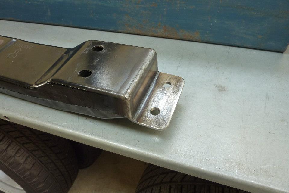 Also from the same piece of 3/6" tubing, cut some angle pieces to cap the end of the cross member and pass under the frame to pick up the threaded mounts that are inside the rail done earlier before boxing it. 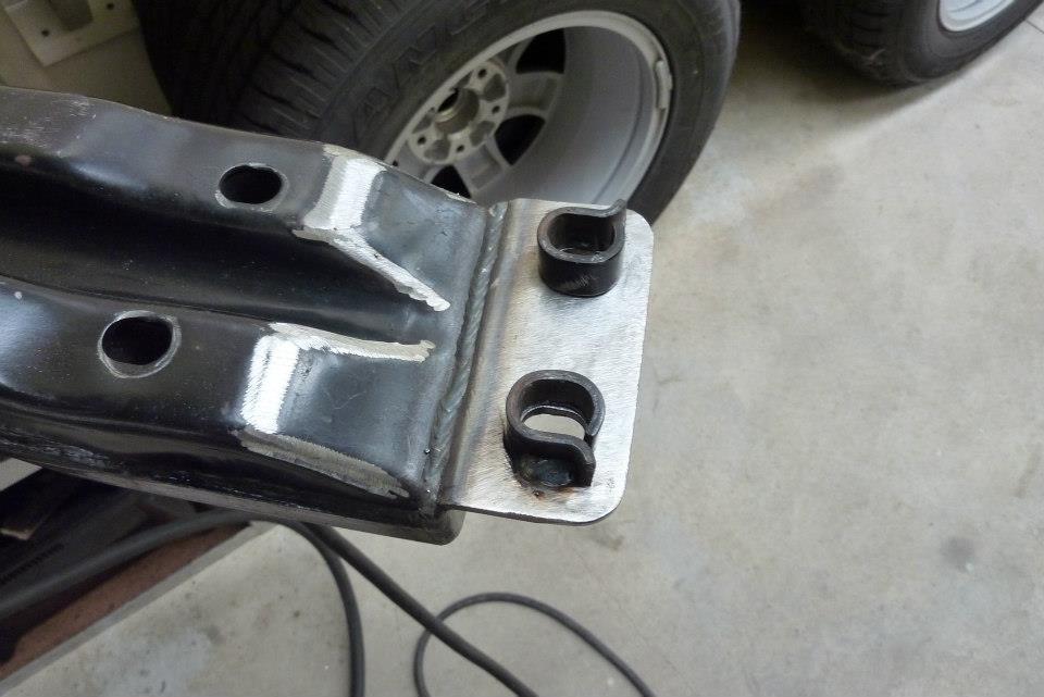 Fitted some anti crush tubes for the slotted holes. I will extend cross member pressing to go over them.  Here you can see how it worked out. This greatly strengthens the mount at the end. 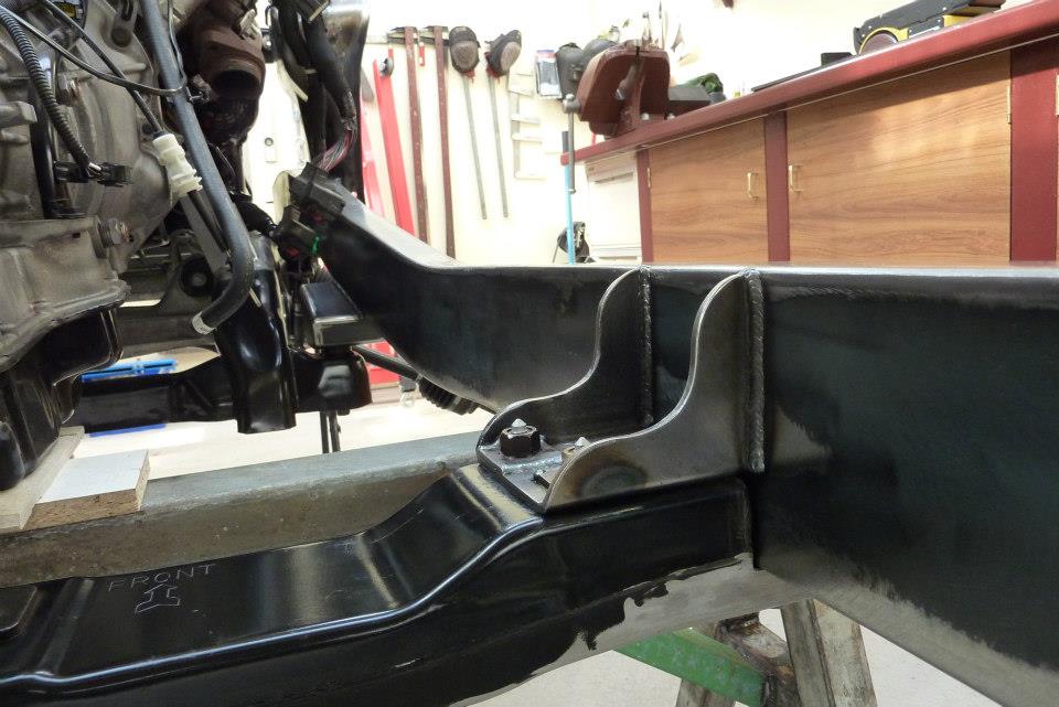 Bracket welded into place. It was first tacked into position after all the bolts were in place. Then the cross member was removed and a sash clamp run from one side of the frame to the other and tightened. The welding was then done one at a time and allowed to cool in-between. This was to keep the frame straight and not bend outwards with the weld heat. 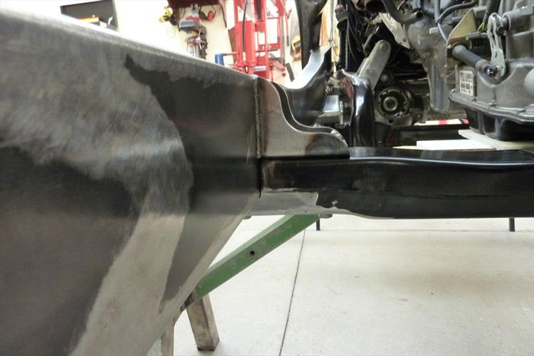 The shape of the upper bracket was to allow the brake and fuel lines to pass by as well as the wiring harness without getting too close to the exhaust which may run down the inside. 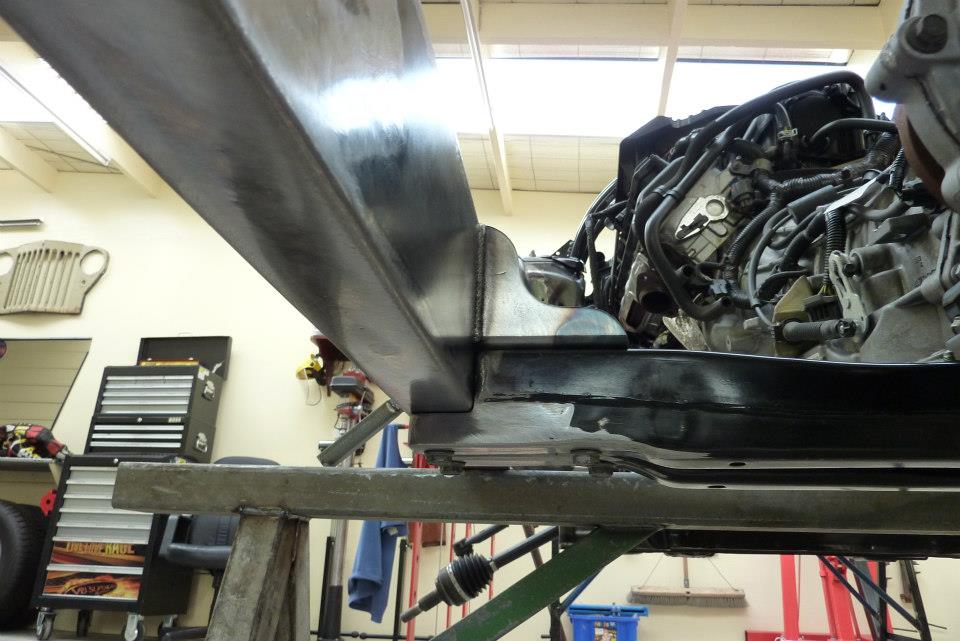 Both inner and outer sets of bolts are at the same height, so no additional ground clearance was lost. 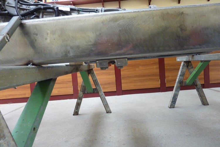 It doesn't look to obtrusive. 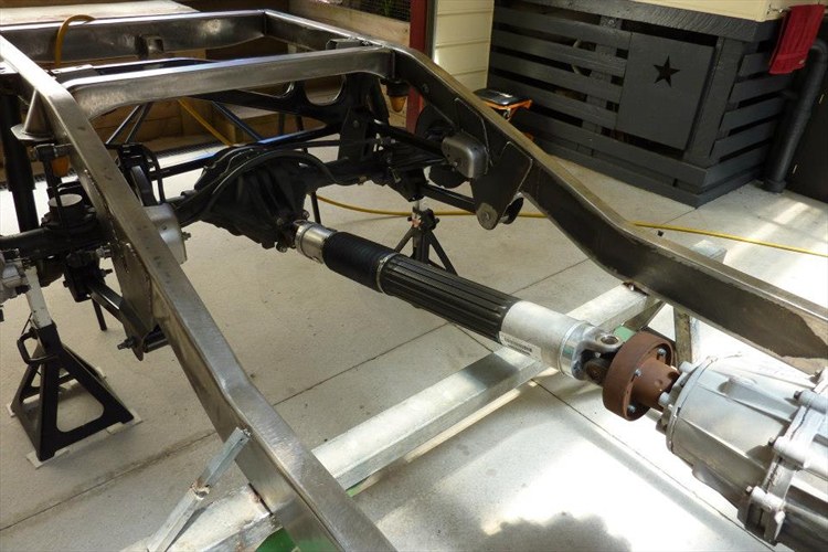 Bolted in the driveshaft to make sure things I fit around it don't interfere. Unfortunately too short to use due to the wheel base differences. 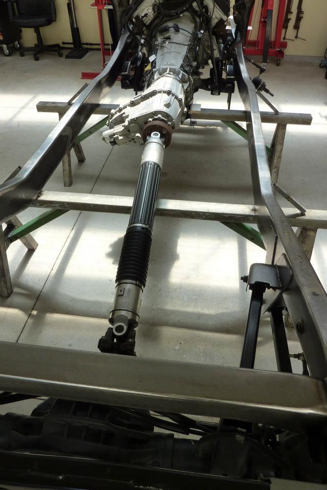 A driveshaft from a diesel or V6 petrol version has the extra 1.5" I need, but are nearly $1500 here! As you cannot replace the uni's on these once worn out, second-hand is not really a option. May machine up a spacer instead if I can get use of a lathe. The transfercase end has the same bolt pattern as a Corolla, so could even use a wheel spacer! 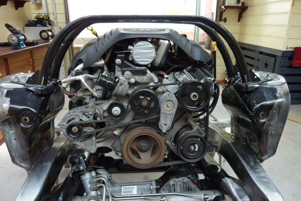 The mount braces still clear the engine fine. 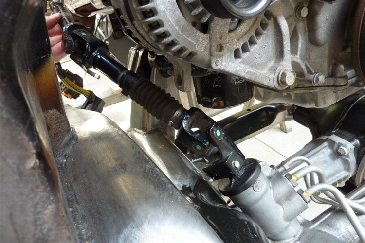 Also plenty of room for the steering shaft. It needs to be extended 7" though to reach the firewall. If anyone knows of another Jeep shaft that may suit, or from other car, let me know please.
__________________
Marcus aka. Gojeep Victoria, Australia http://willyshotrod.com Invention is a combination of brains and materials. The more brains you use, the less materials you need. Last edited by Gojeep; 08-01-2017 at 03:37 AM.
|
 |
| Thread Tools | Search this Thread |
| Display Modes | |
|
|


 Linear Mode

