
|
|
|
#1
 10-05-2014, 07:44 PM
|
||||
|
||||
|
Been asked to post a build thread on here for those who have not seen it before.
The first page of this thread has years later had the rest of the build photos added, so might seem out of kilter with some of the comments made by others. The project is about using a 1948 Willys Pickup frame and cab that will have the full running gear and as much as possible of a donor 2008 Jeep Grand Cherokee Limited added to it, both inside and out. The cab will be made 9" wider and 7" longer using parts from a 58 Willys Pickup. The overall theme is to look like a bigger Willys but 1948 from the outside and 2008 underneath and inside. 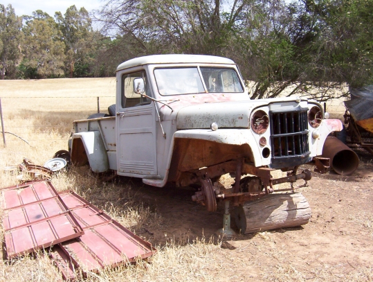 Back in December 2007 I bought a Willys Pickup off eBay but it was a year before I got it home as had nowhere to store it. After much jumping through hoops with the council I built my workshop to house it. 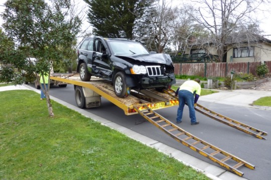 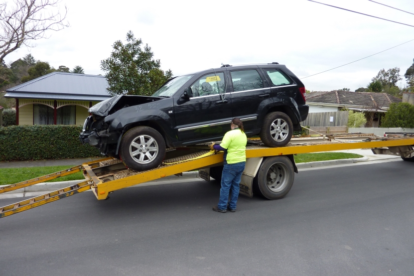 After much looking and watching insurance auctions I was finally able to get a donor for the project. Ended up with a 2008 WH/WK Grand Cherokee with a 5.7 Hemi. It was first registered in 2009 and 12 months later T boned by a Harley rider doing a 100 mph! Hit it so hard that the foot well locked the throttle and he steered off the road into a paddock until he hit a tree. 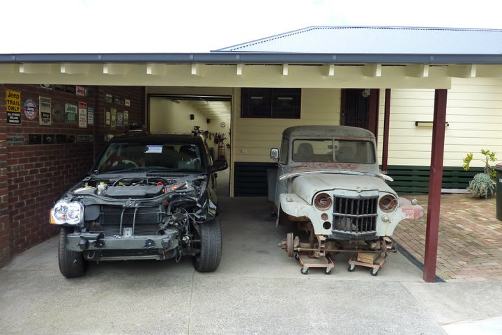 One day these two will become one. 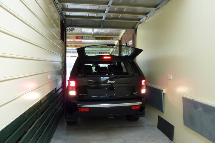 Getting the Grand into the workshop. 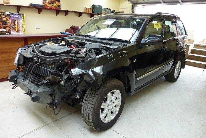 The Grand is in place ready for lots of measurements and then the strip down can begin! 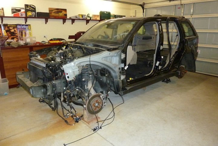 Got a start on the project this week. Started by taking every measurement I could think of so I can setup all the suspension under the Willys when it gets transferred across. Also been labeling every wiring plug that I have found so far. Done the whole engine bay and have it all disconnected ready for removing once I can get to the others ends of the harness under the dash. Also unbolted every panel that can come off and removed the seats. 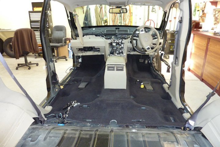 Being careful not to damage any of the trim when taking it apart in case I can sell any that I don't use. 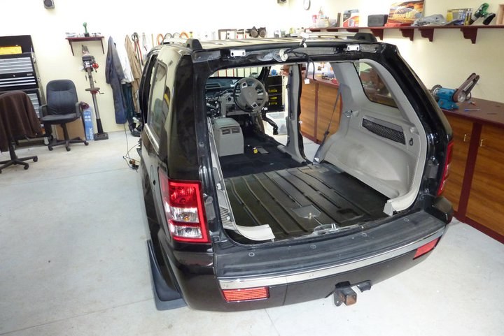 Still go a few more things like the chrome roof bars, rear bumper and tail-lights to go outside. 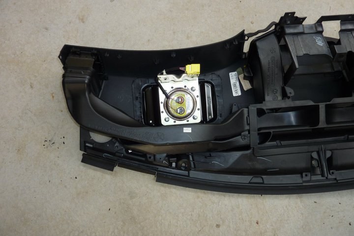 Airbag under the dash cover was quite fiddly to get out. 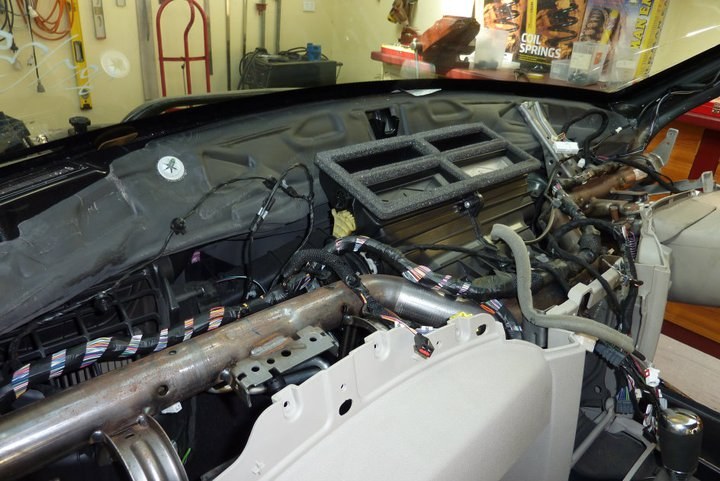 What it looks like under the dash with the top cover off. Going to be fun getting all that into my Willys Pickup later. 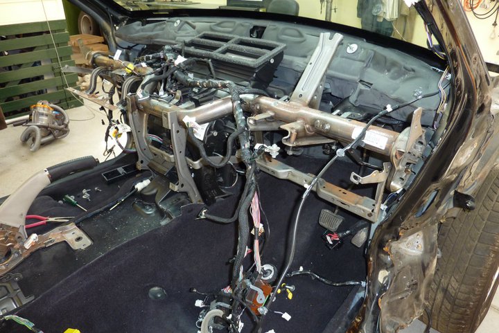 Got the steering column out today along with the centre console and shifter. Just untangling the dash harness and labeling it all. 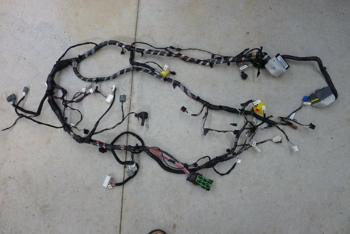 Got my first chunk of wiring harness out. This is just part of the under dash section! 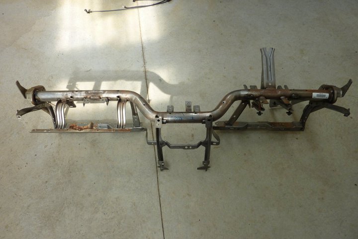 The is the main dash member that just unbolts. It supports the steering column and all the heater/AC parts as well as the radio/navigation and heater controls etc. Planning to install the whole thing into the Willys so I can bolt everything to it like it was in the Grand. 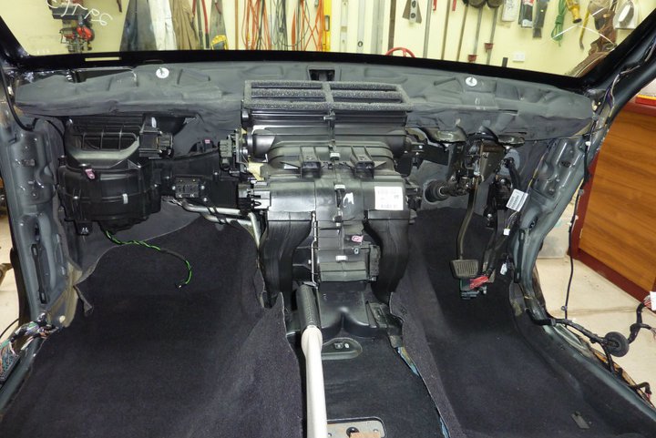 Starting to look a lot less in there now. 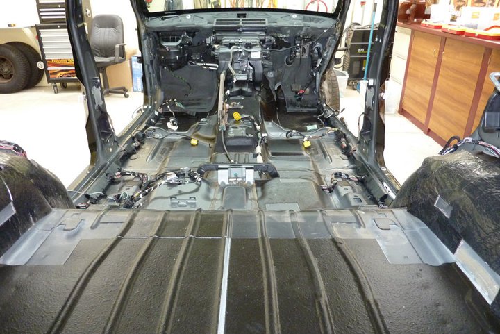 Got all the lining off the sides and seats belts etc out today plus the carpet. More time labeling everything as well. Still have the roof console and lining left to do up top and the HVAC system before I can remove more wiring. Mock up time. This is as low as I can get the front down and the upper wishbone not hit the underside of the front guard and with shorter springs on the struts ( technically coil overs as it has upper and lower wishbones for location ) and still have a decent ride. That is 2.5" lower than stock. I have just placed the Grand's wheels on there hoping the 30" tall tyres would fill the guards enough but not sure they have? Also working out the placement of the front wheel. 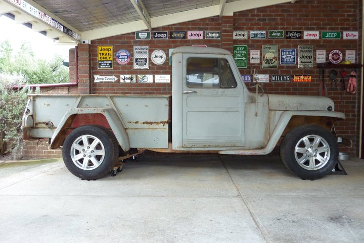 This is 1" further back than stock. 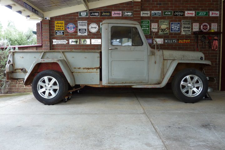 Front wheel in stock location 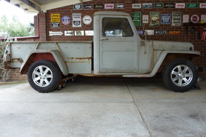 Front wheel 1" forward of stock location 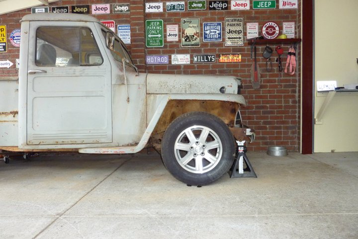 Close up of wheel 1" back from stock. 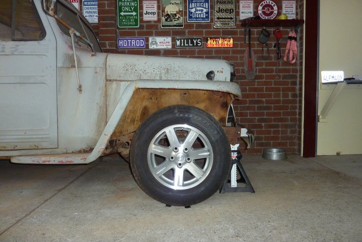 Close up of wheel stock in stock location 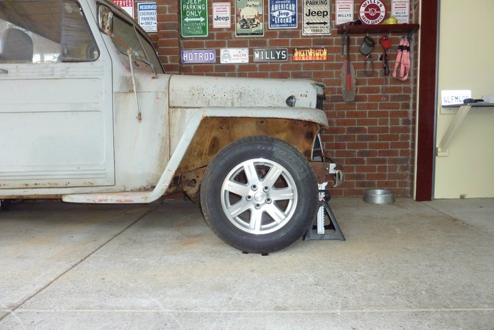 Close up of wheel 1" forward from stock. Few more mock up photos 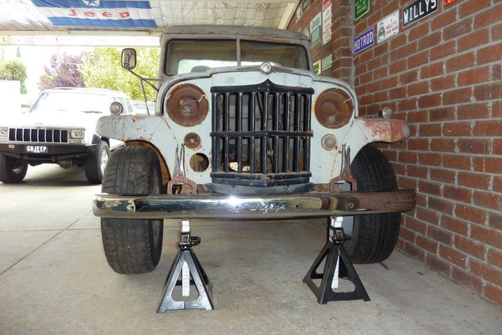 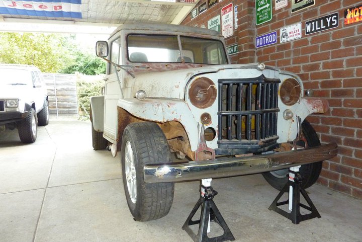 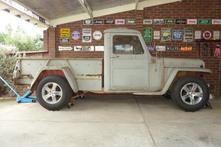 This is with my trailer wheel and tyres fitted. They are a 235x80x17 ( 31.8") instead of the Grand's in 245x65x17 (29.5") in the other photos before this. Had a go with Photoshop for the first time to see how the things I have planned for the body will look on an image I found on the net. 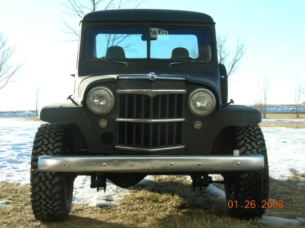 Here is the original photo untouched of a stock Willys apart from the wider tyres. 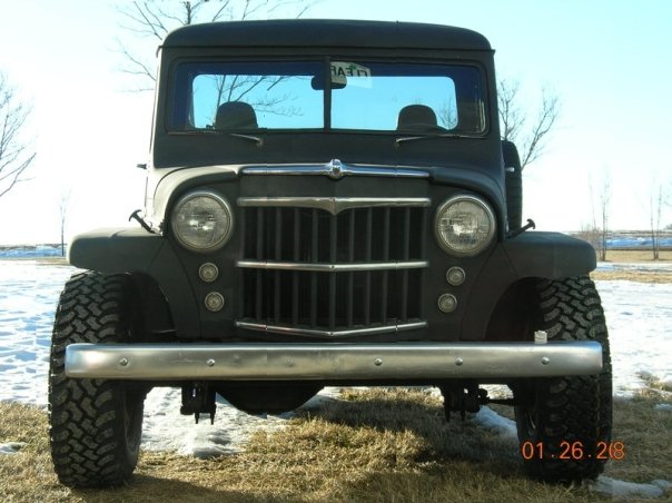 Here I have widened the cab 6" and added an extra pair of lights in the grille. One set will be for parkers and the other indicators. I already have the lights to fit and are LED and look clear until powered up. 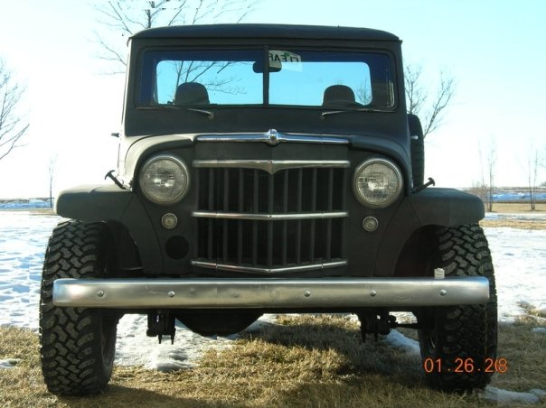 Here I have pancaked the roof or flattened it. The stock roof height looks a little bulbous to me. Checking out what it looks like with a roof chop and the roof pancaked. 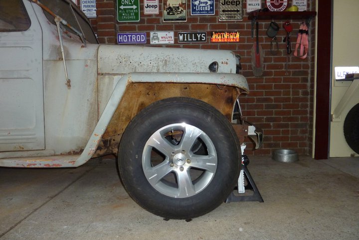 This is the stock axle location as well. 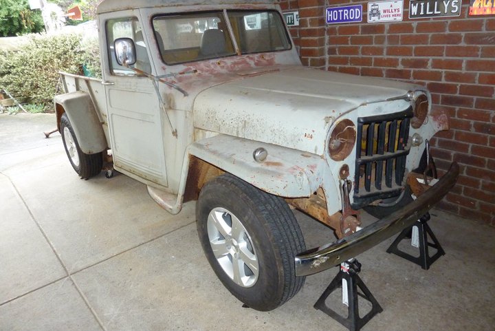 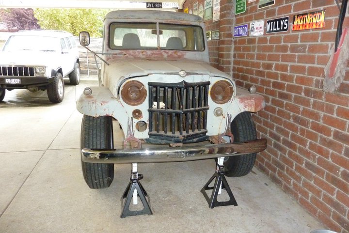 Think the tall skinny look works well with the old truck and hotrod look I am going for. 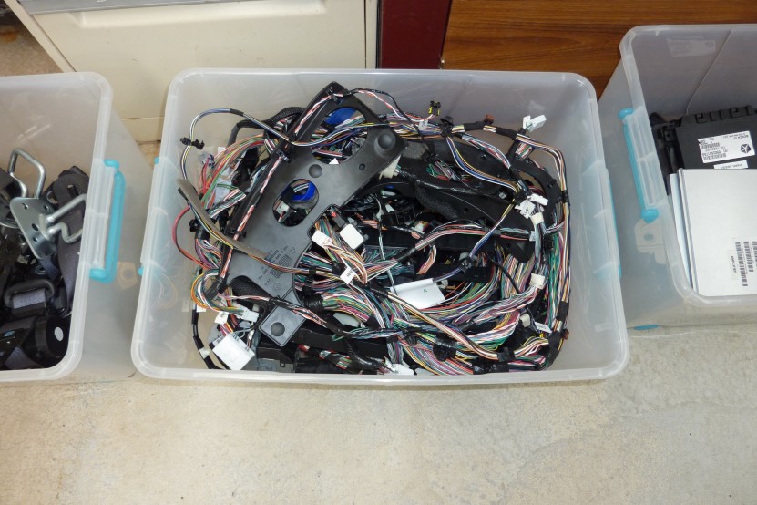 The last of the interior wiring finally out.  I have filled a whole 55 litre tub with just the interior wiring alone and have none of the under bonnet and floor stuff yet. And that does not include another tub I have been filling with the different ECU's, modules etc. I have filled a whole 55 litre tub with just the interior wiring alone and have none of the under bonnet and floor stuff yet. And that does not include another tub I have been filling with the different ECU's, modules etc.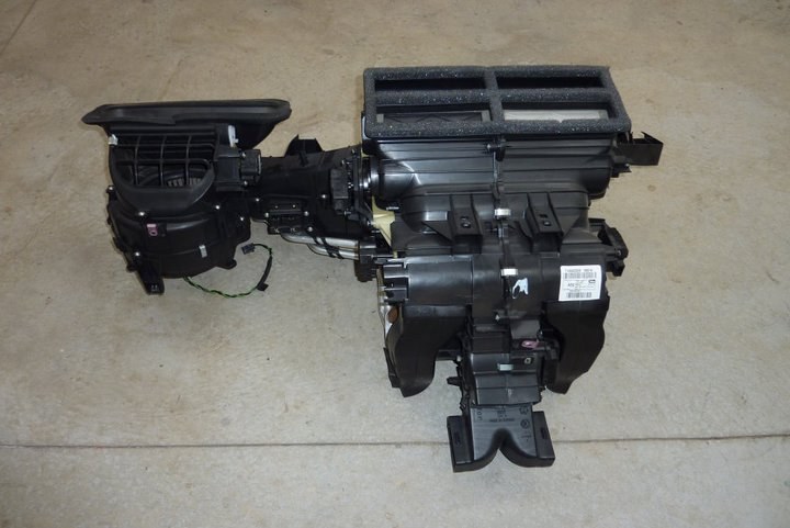 This is the whole heater, A/C unit as well. Hoping to re-use that as is. 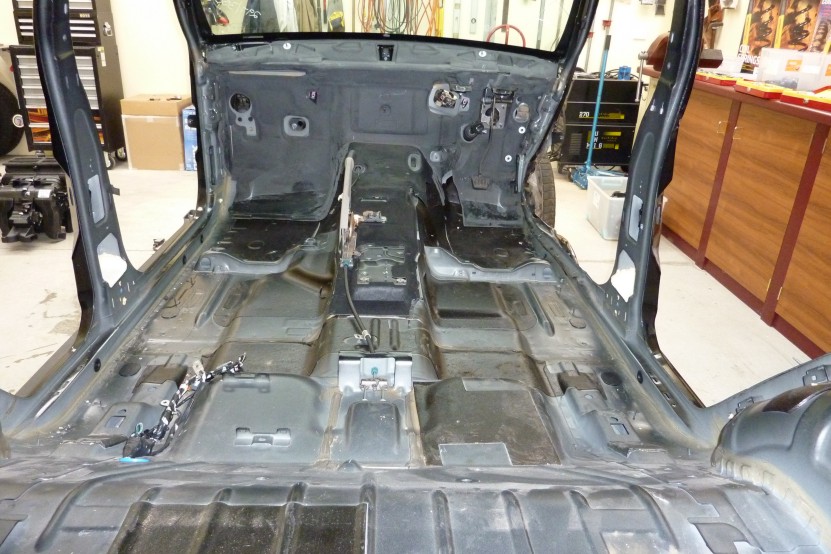 Just a shell now. Only a bit is some firewall insulation left which will come out once I unbolt the brake pedal which has the booster and master cylinder on the other side. Hand brake will come out once I loosen off the cable inside the rear rotors as no adjustment anywhere else. 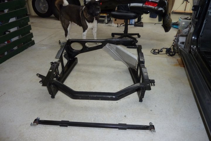 Got the rear frame unbolted. Might think about using it in the Willys as it is also the mount for the panhard bar, tow bar, two exhaust hangers and the charcoal canister. The spare wheel also sit inside it. 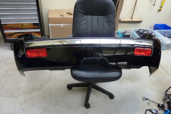 Got the rear bumper off too as well as the chrome roof rails and petrol filler. Everything is ready for it to sit up high on stands so the drive train strip can begin. The strip continues. 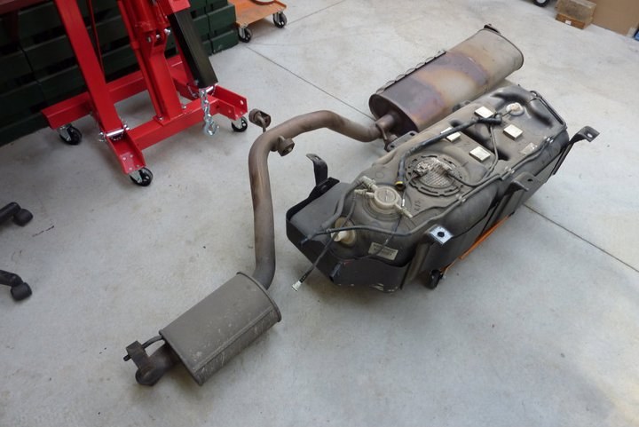 Stainless 2.75" exhaust and fuel tank is out. Huge muffler makes it way too quiet so won't be using it. 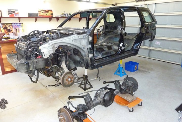 Cut the windscreen out. Then cut it up with my 9" grinder with a diamond blade. Next time though I will wear more than just shorts and sandals as was picking out the glass splinters from under my toes! 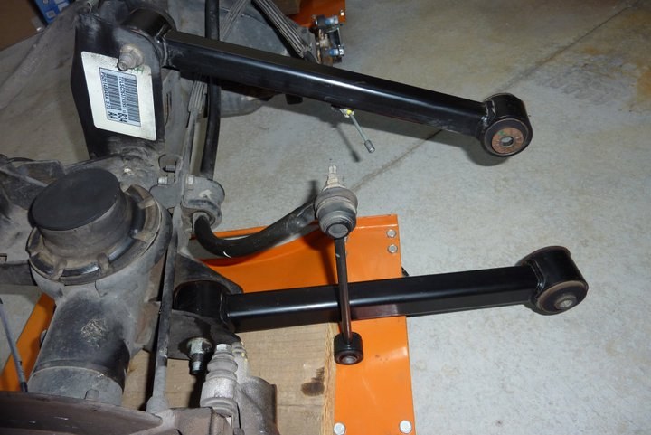 Like the arms on the rear axle. Nice and strong with decent sized bushes. Glad the arms are not the pressed tin ones. 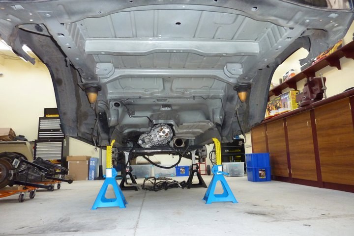 Back end is clear of everything now. I can pick the whole rear up quite easily with all the weight of the engine forward of the front stands. 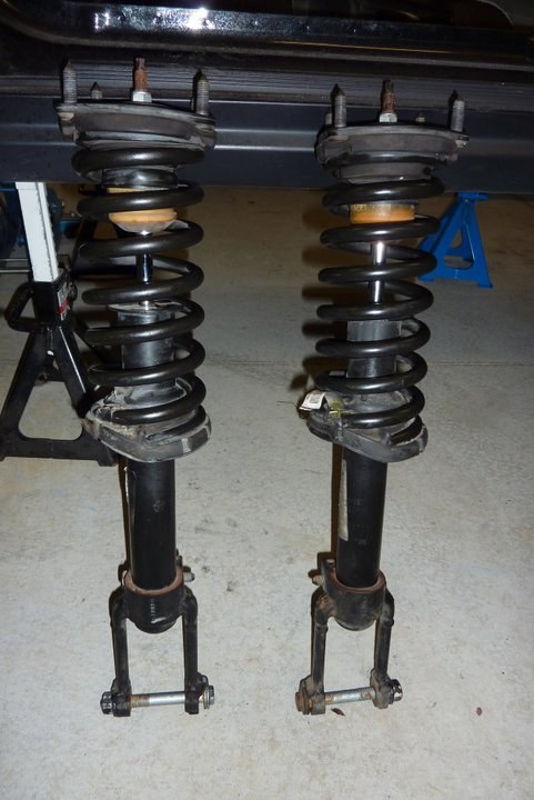 Got the coilovers out tonight. 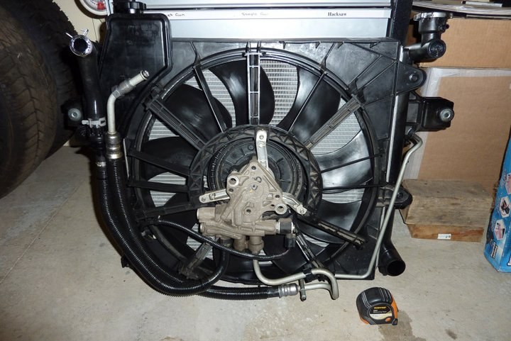 The radiator is pretty big and planning on using it. The AC/ core also has the trans cooler in the top half and the power steering cooler sits in front of that again. The fan is run off the steering pump with electric control by the ECU. Pretty deep though all up at around 9" 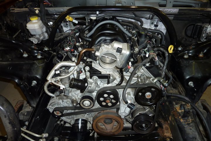 With the radiator out can finally see the Hemi! 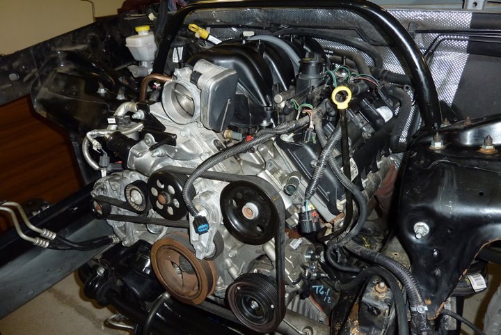 Most of this will be hidden under the engine cover.  There was no way it was coming out through the top with the engine, tans and transfercase still all attached. Also wanted to leave it attached to the sub frame that holds the engine mounts, steering rack, lower suspension arms and front diff. 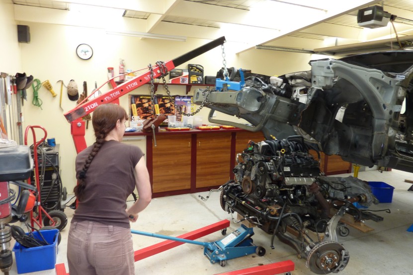 So up up and away. Lisa is manning (should that be womanning?), the engine crane. 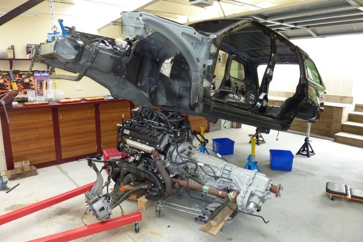 Just look at the size of it all against the big grand for reference! How am I going to fit all that under the little light weight Willys?? 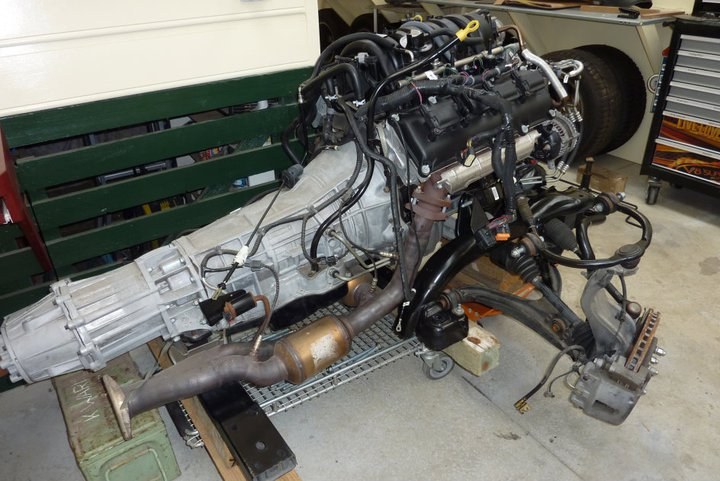 Was hoping to be able to keep everything attached to the sub frame and go up under the Willys as is. Only problem is that the grille is 8-9" closer to the front axle centre line in the Willys than the Grand. The wheels would end up against the firewall. Actual engine bay length is pretty similar ( Willys 3" shorter but there was a couple of inches between the fan and the front of the engine), so that is good. 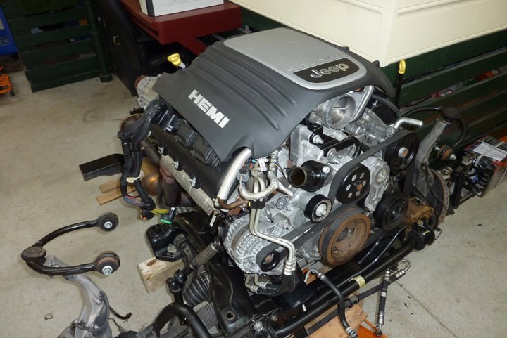 Looks good with that cover on. 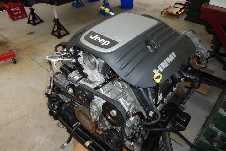 Cover is actually a bit short to clear the forward upper cowl area of the Grand. Wonder if the cover from a 300C, Challenger or Dodge truck are longer that these engines also come in?
__________________
Marcus aka. Gojeep Victoria, Australia http://willyshotrod.com Invention is a combination of brains and materials. The more brains you use, the less materials you need. Last edited by Gojeep; 03-07-2020 at 07:20 AM. 
|
|
#2
10-05-2014, 08:08 PM
|
||||
|
||||
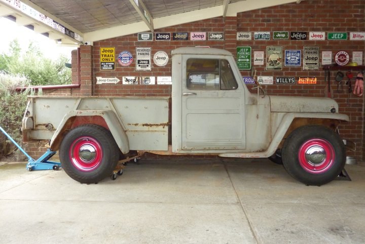 I was lucky enough that someone gave me a photo of their hotrod with red steelies on at a similar angle to mine, I was able to crop the wheels out and add them to my 32" trailer tyres. Think it looks pretty good. Now as I am going to widen the whole cab 7" to match the width of the rear and cover the new front end, I want to stretch the cab length ways also to keep the proportions and get more leg room. So this is at stock length. 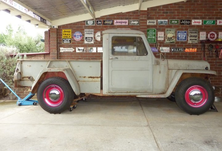 This shot shows the cab lengthened 3.5", or half the 7" I am widening the cab. The bed is shortened 3.5" to keep the overall length the same.  Here I have stretched the cab 5.5" which is the same percentage as the cab will be widened, (13.5%). I took the cab length to be from rear of cab to the base of the windscreen. The bed has been shortened 5.5" as well in front of the rear guard leaving the wheelbase the same as stock. 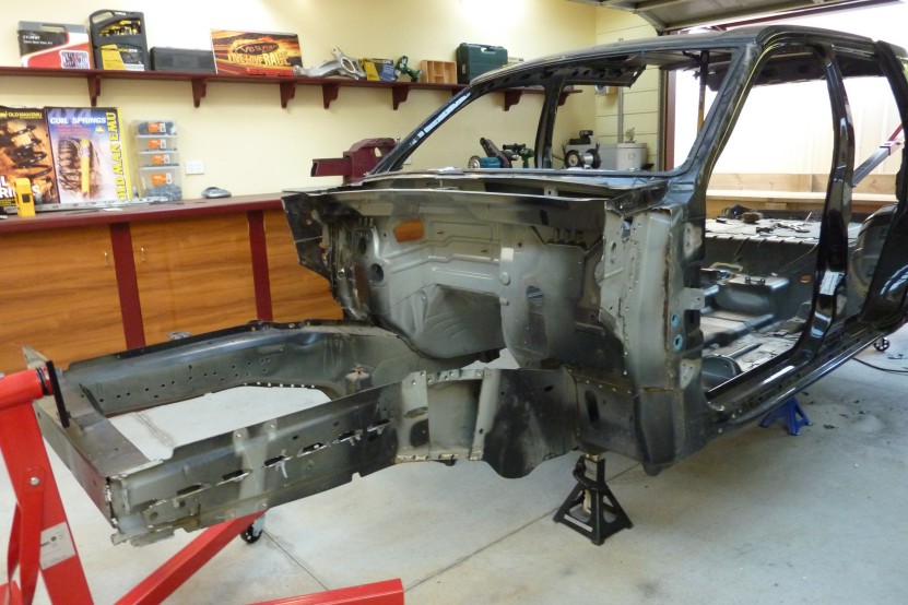 Got the coilover and upper wishbone mounts off and will use them on the Willys frame once it gets spread to the same outer width as the Grand. Also got the mounts out from inside the frame for the front of the sub frame. Was a pain as lots of spot welds and stitch welding on the outside. 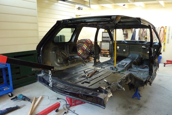 Decided to remove the rear quarters as hoping to be able to sell them to the Jeep wrecker as nothing wrong with them. Driver side off. 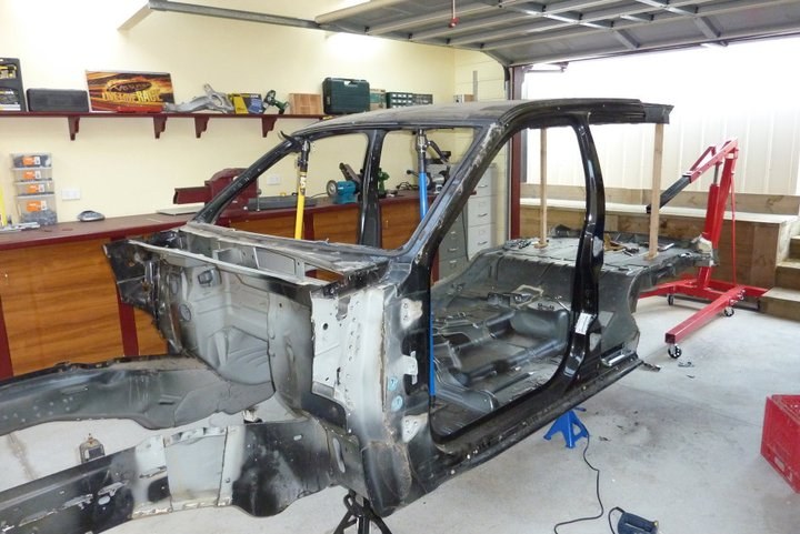 Passenger side quarter panel off too. 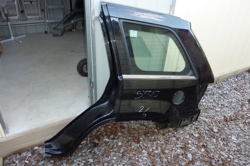 One 1/4 panel. Hopefully can sell it off one day.  Got the firewall on this side mostly unpicked. 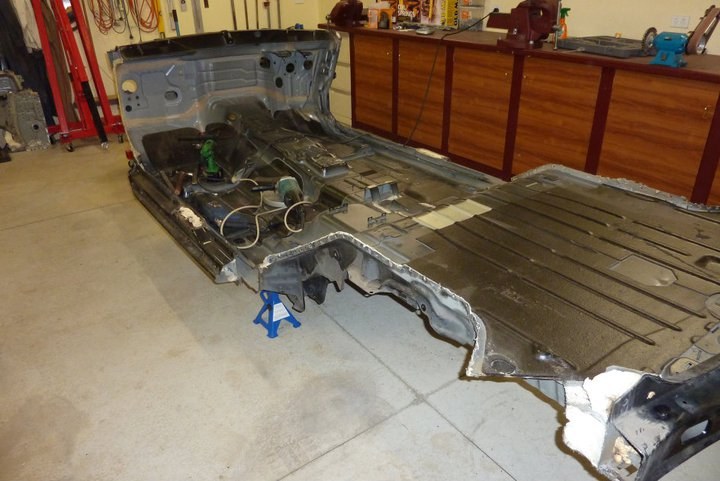 The damaged side on the right will be harder to remove as all squashed together. Will need quite a bit of straightening before I can use it, but will be much easier once the kick panel area is gone.  Not much progress to show worth posting about but still forging ahead between other things that get in the way of the project like normal. I made a quick rotisserie out of two Aldi engine stands that cost me less than $100 for both of them. Can't buy the casters for that let alone the thick plate the pivot is on and other steel used in the stands etc. 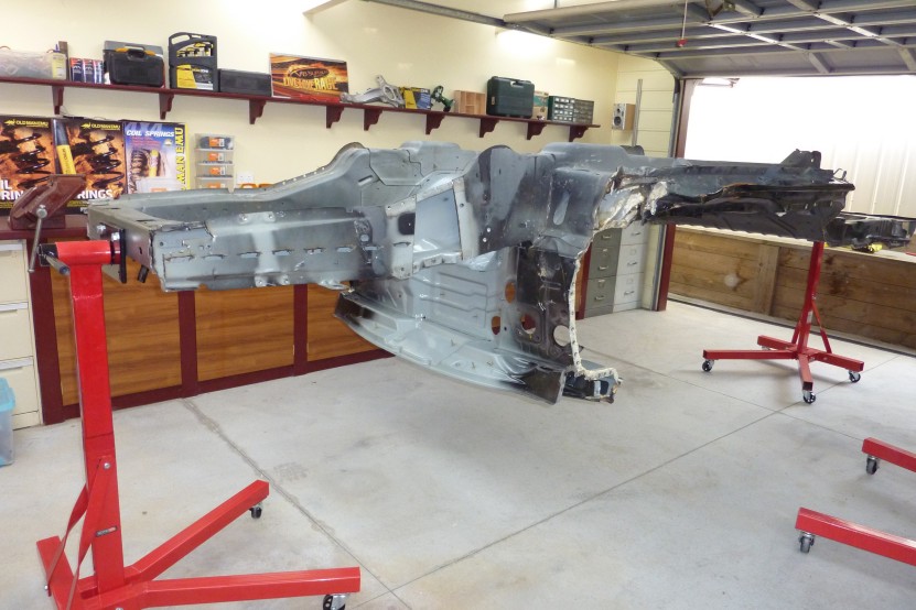 Lifting up what is left so I can attached it to some raised engine stands I made up to make this next job easier and safer.  Stands are higher than needed for this part of the job but I will use them also for rotating the Willys cab as well. Had to use the old Pythagoras rule for working out length of the hypotenuse, so I can know how high the pivot point needs to be. Squared the height of the cab, then added the squared width and then square rooted the result. A2+B2=C2 Halved the answer to get where the pivot point should sit and still be able to do a full rotation without hitting the floor. Just as well I paid some attention at school as never know when you may need that knowledge.  Decent sized rails underneath with over 300 spot welds holding just the forward section of the floor I need on. Door sills were very robust as well and a double section. Much drilling to go and then can start drilling out all the suspension brackets and coil and panhard mounts etc too! 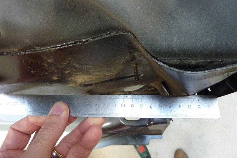 As I will be using the firewall and floor, I had to repair the damage from the Harley that hit the side at 100 mph according to police estimates. Thought it would be easier while still up on the rotisserie for a good working height. Also much easier to flip it up either way depending on which side I am working on. The ruler gives you an idea how much it needs to be straightened. 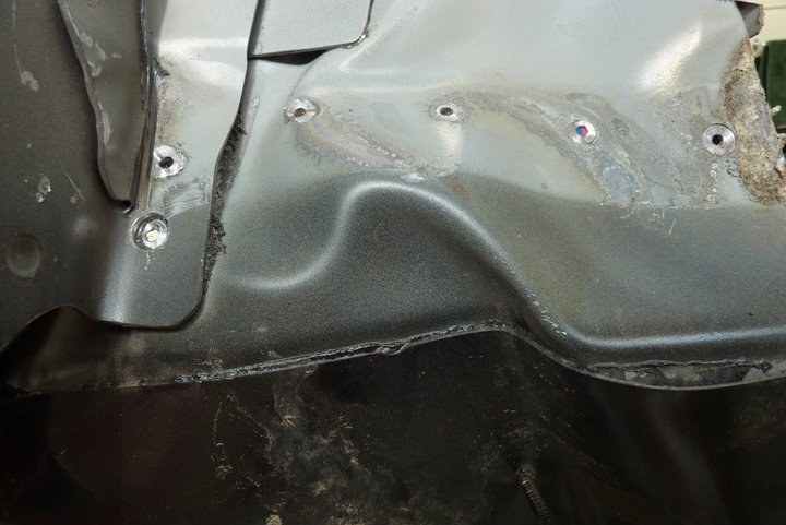 This crease is pretty sharp. This photo shows how much the force moved it. You are looking at the firewall upside down and this is where it goes from vertical to curving into the floor section. 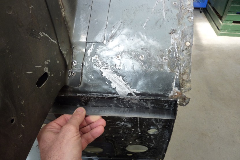 Looking a lot straighter now. Need to work the upper section some more but will do that later once off the frame as some buckling still under that section. 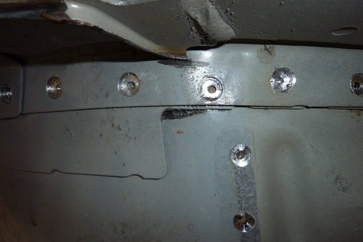 Still busy drilling out all the spot welds to remove the floor from the uni-body frame 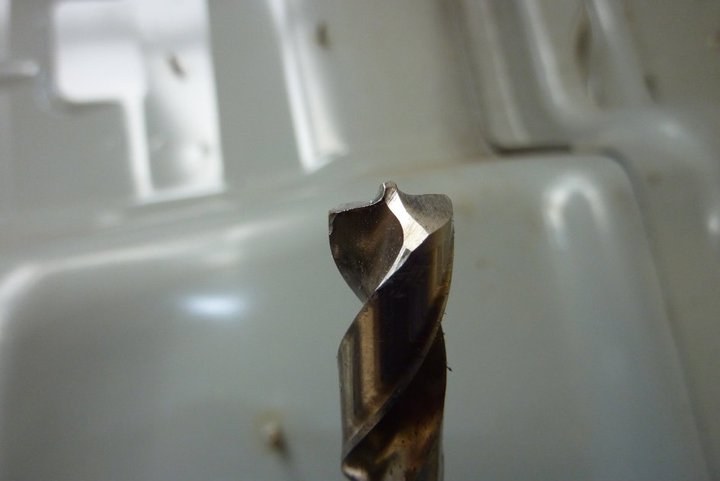 I have ground the drill bit into what called a pilot point. These only work once a pilot hole has been drilled first. Then the centre part of the drill sits in this to locate the bit and then the cutting edges are almost flat to give a very shallow cut. The angle is less than what shows on this angle of shot.  You can see that all the drill holes on the lower part of the picture is what is left after only drilling the large hole through the top layer of the spot welded metal only. Much easier to just weld the small pilot hole up then the whole spot weld size. 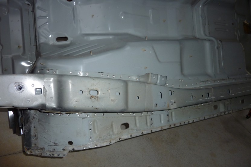 But as you can see there is an awful lot of them to be done!  Finally after 400 odd spot welds drilled out, the floor and firewall is separated from the uni-frame. Quite substantial as 4" deep and further reinforced with another hat section inside of that as well. Good to see how well all the galvanized steel is coated through and through. Was even between each layer of steel also.  Will be leaving the floor stiffener in place as it is the rear mount for the seats and seat belts. I did quite well on drilling out all the spot welds too with one or two one breaking right through the floor panel that I wanted left undrilled apart from the pilot hole. There was a few others when a bracket had to be removed from the top side as well so had to be drilled from both sides, but not bad going when you have to stop the drill bit each time only 1.2mm short of drilling through. Learnt a trick right near the end of tapping in a cold chisel into the joint and then you would here a crack just as the spot weld broke from the floor. Of coarse only discovered this with less than a dozen to go! 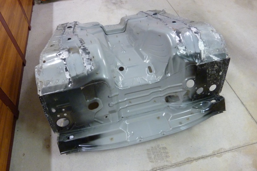 Not sure if I can keep where the cowl juts out or not. It was for the air intake for the heater and A/C and where the wiper motor and linkages sit. Not useful for either as they are needed under the cowl in the Willys and not the bonnet where this sits in the Grand. 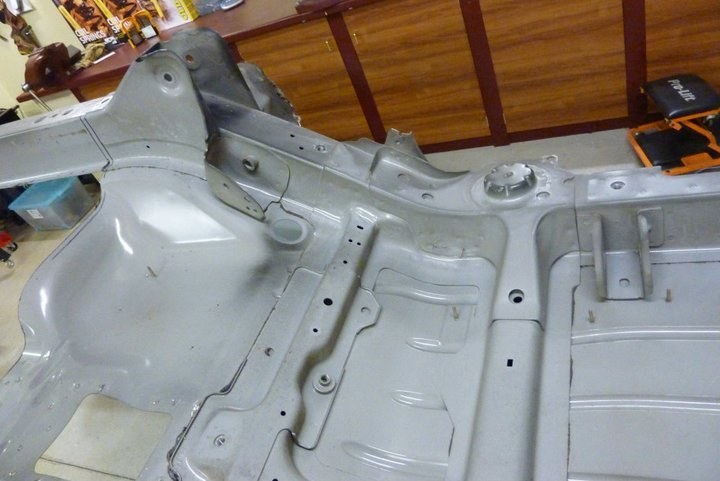 Still undecided on how to best use the rear suspension mounts. At the width it sits, the rails with upper and lower control arm and coil mounts would nearly fit between the Willys chassis whole. So could leave them mounted to the rails and weld this to the inside of the Willys chassis. I will keep this section as one piece until I know how to use it best. Want to use the mounts either way and they are made from HSLC ( High Strength Low Carbon ) steel and is 30-40% stronger than normal steel and has a higher corrosion resistance as well. Finally after 400 odd spot welds drilled out, the floor and firewall is separated from the uni-frame. Quite substantial as 4" deep and further reinforced with another hat section inside of that as well. Good to see how well all the galvanized steel is coated through and through. Was even between each layer of steel also. Will be leaving the floor stiffener in place as it is the rear mount for the seats and seat belts. I did quite well on drilling out all the spot welds too with one or two one breaking right through the floor panel that I wanted left undrilled apart from the pilot hole. There was a few others when a bracket had to be removed from the top side as well so had to be drilled from both sides, but not bad going when you have to stop the drill bit each time only 1.2mm short of drilling through. Learnt a trick right near the end of tapping in a cold chisel into the joint and then you would here a crack just as the spot weld broke from the floor. Of coarse only discovered this with less than a dozen to go! Not sure if I can keep where the cowl juts out or not. It was for the air intake for the heater and A/C and where the wiper motor and linkages sit. Not useful for either as they are needed under the cowl in the Willys and not the bonnet where this sits in the Grand. Still undecided on how to best use the rear suspension mounts. At the width it sits, the rails with upper and lower control arm and coil mounts would nearly fit between the Willys chassis whole. So could leave them mounted to the rails and weld this to the inside of the Willys chassis. I will keep this section as one piece until I know how to use it best. Want to use the mounts either way and they are made from HSLC ( High Strength Low Carbon ) steel and is 30-40% stronger than normal steel and has a higher corrosion resistance as well.  Well that is the last of the Grand Cherokee cut up and carried out of the workshop. Next phase will be bringing the Willys back in and doing lots of comparative measurements to workout how best marry the two! 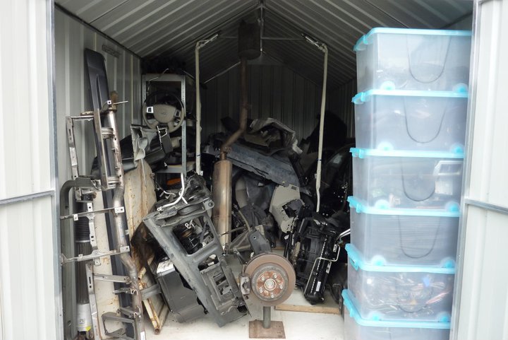 The poor little shed is busting at the seams! Managed to fit nearly the whole Grand in there apart the rear quarters, roof and rear floor plus the front sub assembly. Cant wait to start taking things back out of there as means I am actually putting things back together or sold some parts I don't need. 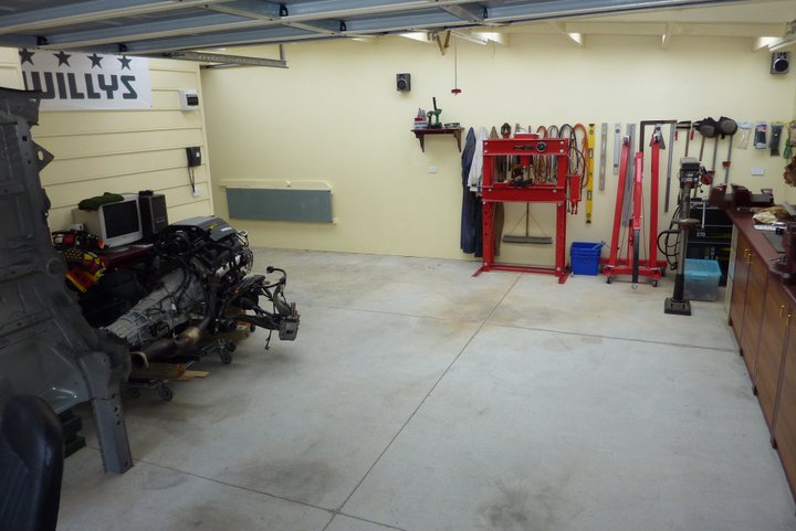 Been a while since there has been a clear floor. 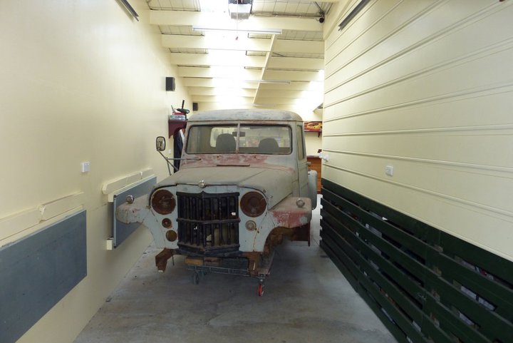 Willys going into the workshop. This is why I made my benches fold down easily. Tight, but it fits.  Hard to believe that that engine will one day sit in the Willys. 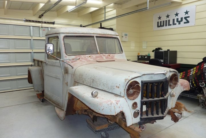 Ready to be set at the height where I will take the measurements I need before pulling it apart. Got the fun of trying to think of every thing needed before strip down begins. Takes a lot of time with nothing to see for it, but essential all the same. 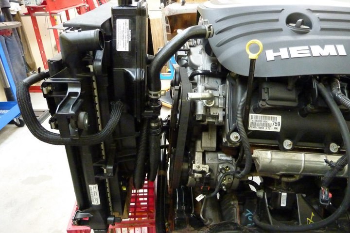 I was able to have the radiator nearly 3" closer than what it was in the Grand. Will still leave me enough room to change a belt. I was careful when removing the drivetrain to keep it at the angle it will remain at once installed. The radiator has also been set to the finished angle to get a better idea of working room behind it. 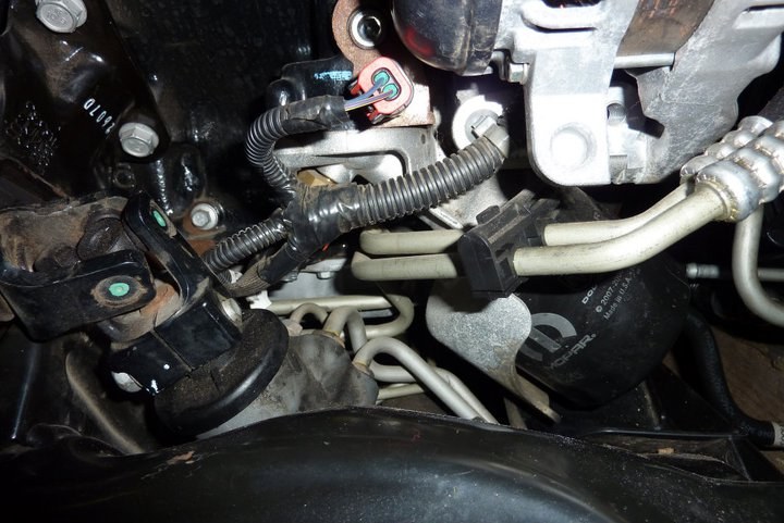 Another problem I ran into was that because I have to move the axle, steering and suspension etc forward 6" to centre the wheels under the front guards, the oil filter will end up on top of the steering rack. Not a problem for a LHD, but it is for me. But it looks like I can just remove the whole angled filter mount and spin the filter directly onto the block instead and have it vertical. 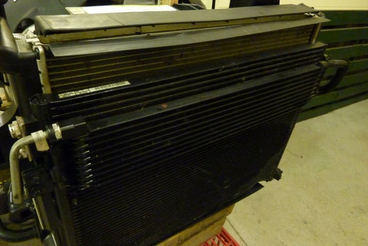 If I want to mount the Grands firewall in the stock Willys location, I will have to come up with a different power steering and hydraulic fan cooler. Would save loosing interior space, even if it is only a 1.5", but am extending the cab anyway around 6" so not that much of a concern. If I do move the firewall back that far though, I can use the Grands stock aluminium rear drive shaft. Also moving it back will give me a bit more depth in the dash in front of the windscreen to mount my instruments that in the Grand sat in a leather clad pod into the top of the dash. Will also compare door opening to firewall depths between the two vehicles. The other thing is the cowl vent might end up partially over the firewall so has to be checked as well. Fun and games. 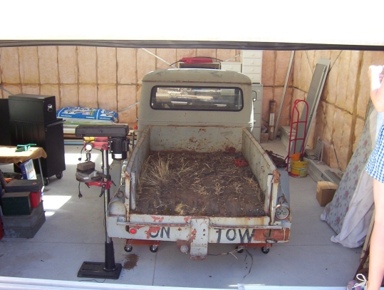 Got a few hours spare to at least do some clean up in the back. 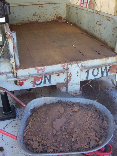 Been spending a lot of time before that working out exactly what needed to be done to fit the suspension and drivetrain into the Willys frame. I don't want this sitting jacked up in the air as want good road handling, but it wont be sitting on the ground either as not the theme I am going for. It must remain perfectly practical for interstate drives etc. My limiting factor was the underside of the front guards. I can only drop the body over the suspension until the upper front wishbone, at full compression, does not hit the underside of the front guards. To get the whole Grands sub frame to sit under the frame to get that height, I have to step up the height of the front of the chassis by 2" while leaving the chassis under cab unchanged. 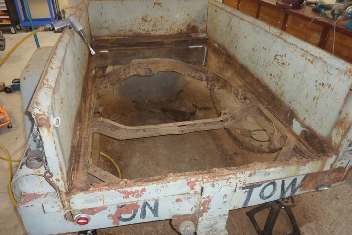 Who says I don't ever get the floor dirty! Was a good bucket full to clean this up. 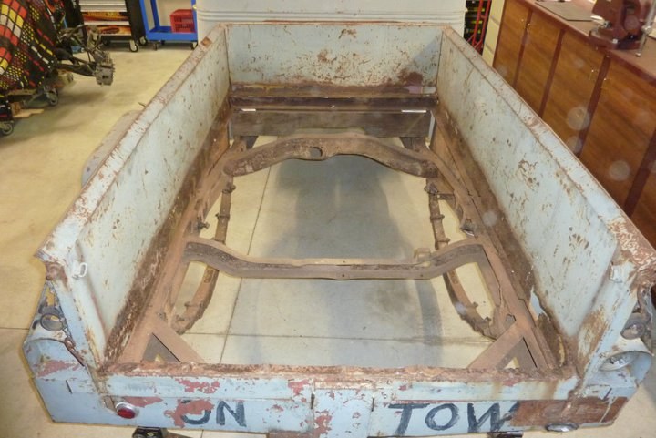 So now have the floor and its cross members out and the fuel tank. In the rear the frame will be kicked up 4" and will be running level with the top of the old cross members that supported the floor. I intend to drop the floor cross members in between the frame rails to keep it low in the stock position and so there is no big step up when you open the tailgate. The 4" rise will mean I can install the rear suspension at the same relative height as it was installed stock in the Grand compared to the front. This keeps the roll centres front and rear at the same height as when installed in the Grand. All suspension points, including upper coil mounts, will be made to be at the same height as well so will be running stock control arm and panhard angles. Any further ride height adjustments will be fine turned with different coils front and rear. 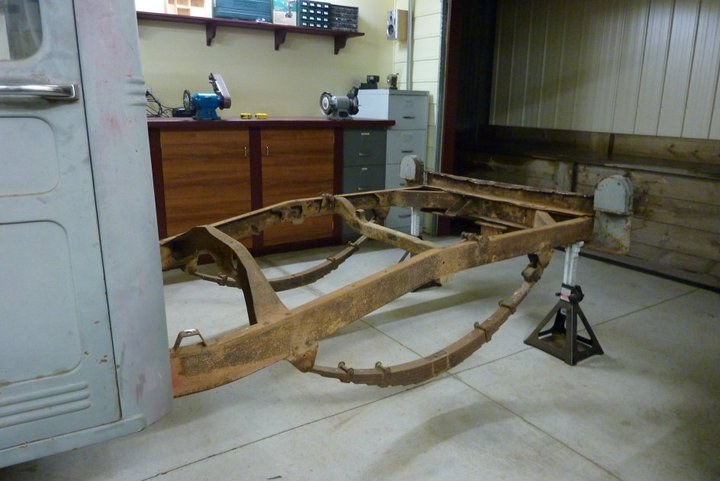 Bed is cut up and gone. Just got to workout how to remove the 8" channel that has been used as a rear bumper, and even bent, along with 3/4" plate for a hitch point. 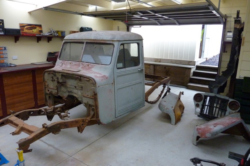 Got the monstrosity of a rear bumper made from 8" channel cut off. 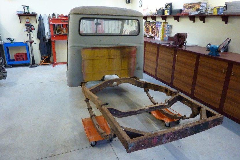 Got the front panels all off and didn't even break a single bolt! Spraying them with WD40 once a month for the last year must have paid off. 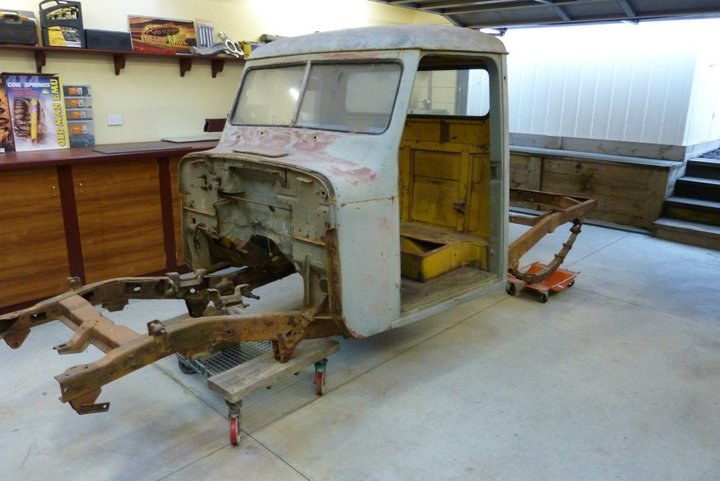 Door just came out easily too. Was ready shocked as these only have Phillips head screws holding them on which are prone to stripping. 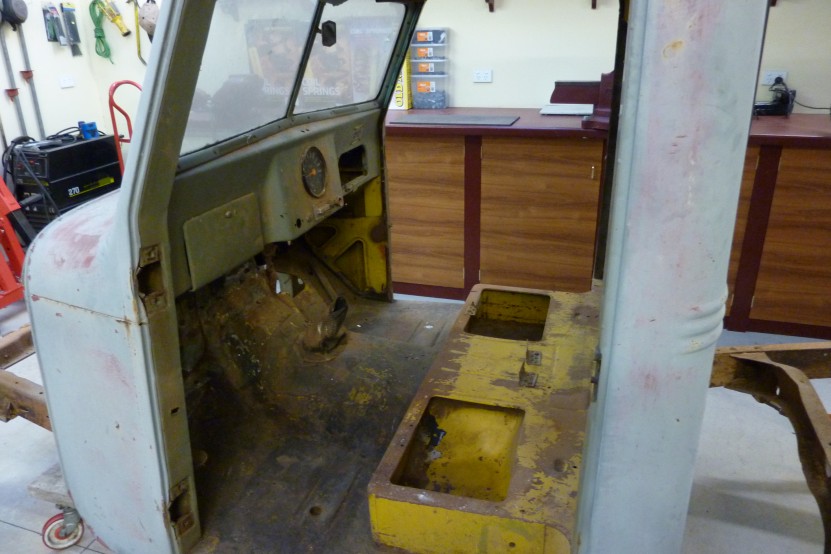 Cabs all cleaned out and ready to be lifted off.  Woo hoo, time to lift off the cab. Rolled the chassis and cab under my carport in front of the workshop where I still have this winch setup. It is a boat trailer winch that is though bolted to the centre carport post. The cable then runs over a pipe that it bolted between two rafters. The lifting frame was when many years ago I had a roof top tent that I made this setup for so I could simply park under it and remove or install it by myself. Just left the camper pack sitting up in the air the rest of the time. 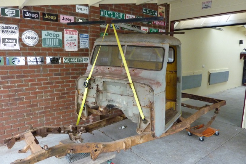 We have lift off. Was very easy and fuss free and my wife even did all the winching by herself. 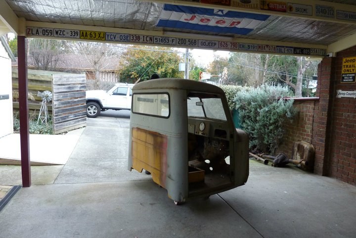 Back down on a old shopping trolley base ready to go for a ride. 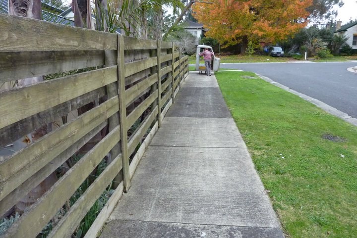 Got some strange looks as we had to go up the footpath. 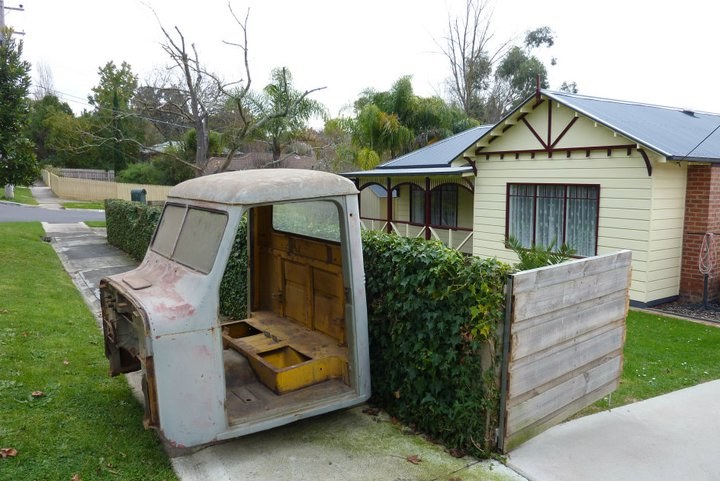 And around the corner to the front of the house. 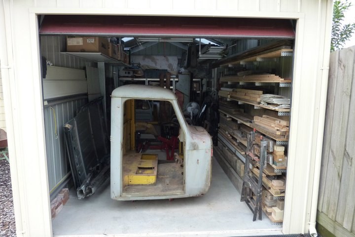 Will sit in the garage where the camper trailer normally lives until I am ready to work on it. 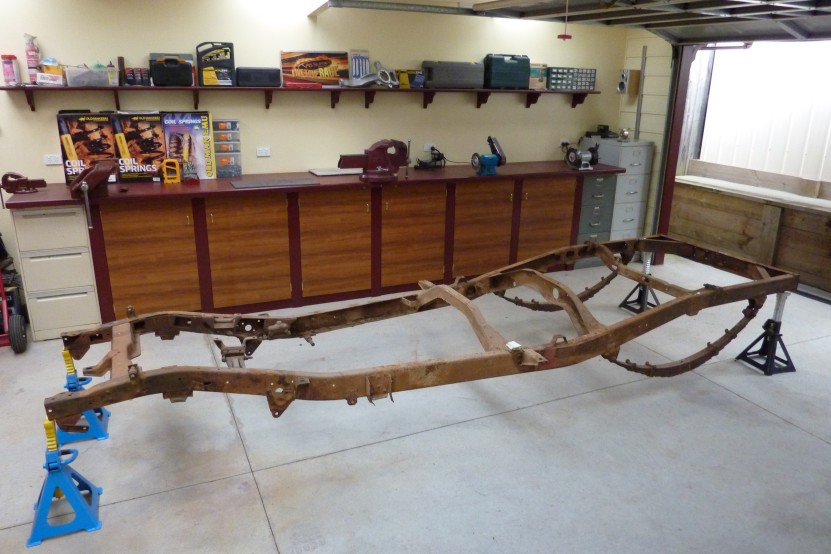 Chassis is now ready for the big strip down. Heard it can be quite hard removing all the frame rivets and there are plenty of those holding every bracket and cross member in. Hoping grinding the head off and then using an air chisel with a punch bit will work. Got some rose welds to try and remove as well without damaging the cross member inside the rail. 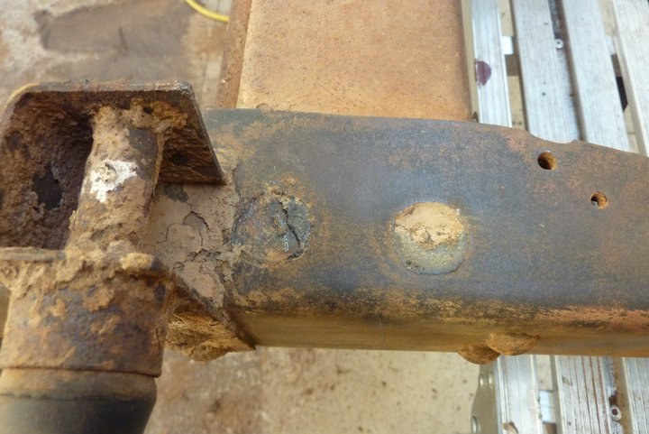 Had a bit if think of the best way to remove these big rosette or plug welds which hold the front cross member in. I didn't want a big hole left in the front cross member after wards as well as might be reusing it.  So thought I would use the same drill bit I ground up to take out the spot welds, as it drills flat rather than a chamfered hole, and stop before going into the cross member. You can see one done now and the next one ready with the pilot holes drilled. 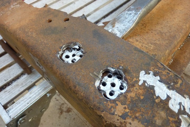 Didn't need to drill the center hole in the end so didn't drill that when doing the other side. It easily broke free when I drove a cold chisel in a bit. 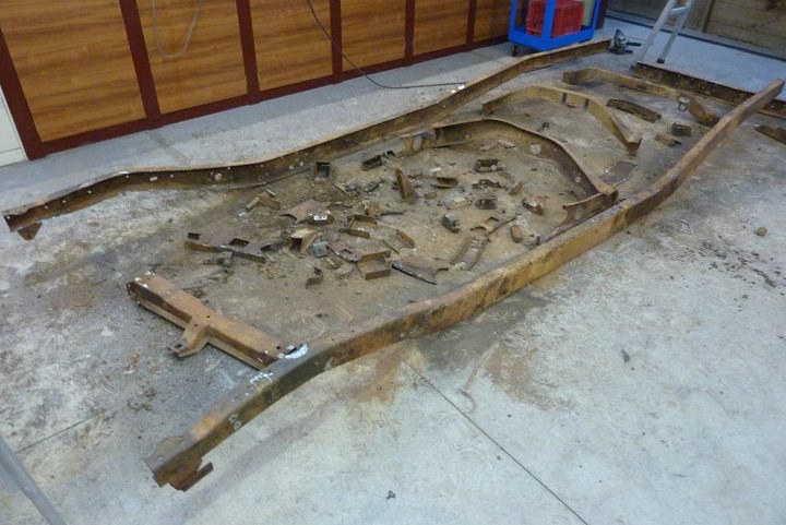 What a MESS! Who would think a frame could hold so much dirt. Seeing this Willys came off a potato farm until it was sold off when he was done for cultivating drugs, it is not surprising! Maybe I should keep the soil and water it to see what come up! There is just so much more to remove than just the cross members to get down the bare rails. 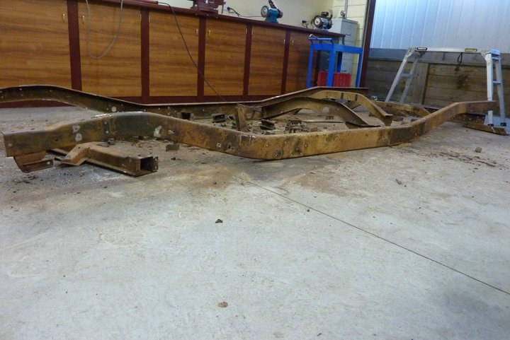 This angle gives you a bit of idea how much kick up the frame has at each end. I will be increasing that by another 2" front and 4" rear. Now I must be off to clean the workshop.
__________________
Marcus aka. Gojeep Victoria, Australia http://willyshotrod.com Invention is a combination of brains and materials. The more brains you use, the less materials you need. Last edited by Gojeep; 03-07-2020 at 07:03 AM.
|
|
#3
10-05-2014, 08:09 PM
|
|||
|
|||
|
Marcus, you have a bit of a challenging and exiting project ahead of you. I like your idea of using late model equipment.
You will have that Early rugged look with the Ohh-La-Lar comfy feeling on the inside with power to match under the throttle. Looking forward to the progress, on this one. Cheers John
__________________
John EK Holden V8
|
|
#4
10-05-2014, 08:17 PM
|
|||
|
|||
|
I love old Willys! My first vehicle was a '59 Willys wagon. As alittle boy i rode in my dad's '48 wagon. Those things bring back a lot of memories
__________________
Mike
|
|
#5
10-05-2014, 09:13 PM
|
||||
|
||||
|
Looks like a great project and I'm looking forward to seeing it all.
__________________
Kerry Pinkerton
|
|
#6
10-05-2014, 10:26 PM
|
||||
|
||||
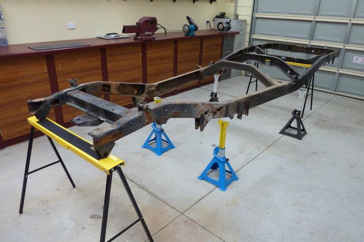
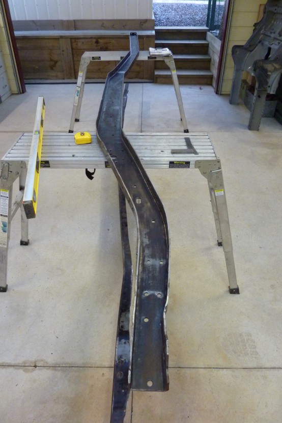 Rails have come up much better than expected after several hours of grinding and wire brushing them clean. Only thing is I counted a 111 rivet holes that will all be needed to be welded up in each rail.  This gives you an idea of the frame bends horizontally before I start modifying it to suit the suspension pickup points of the donor Grands rear and its front sub frame. 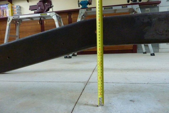 Rear height where the coil mount will sit. Will increase this by 100mm/4" 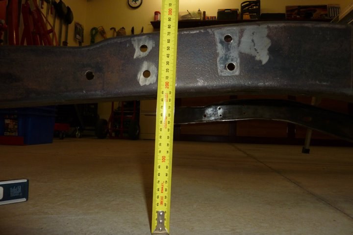 This is the starting height at the front of the frame rail where the front mount of the Grands sub frame will bolt in. Will have to raise this point by bending the front of the rail upwards. 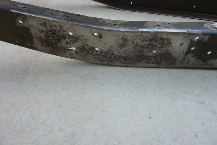 This is the only rust on the whole frame and at the same place on the other rail too. It is where the frame kicks up behind the cab. This happened as some one had added a extra plate to the outside which was only stitched welded on and the gaps let the water and dust in. Rail is bent more than it should be slightly at this point which is fine as will be bending it more anyway. Thinking of cutting this section out, but leaving the flanges, and adding in a new piece with the extra curve in it that I need, and then bend the flanges to suit it. 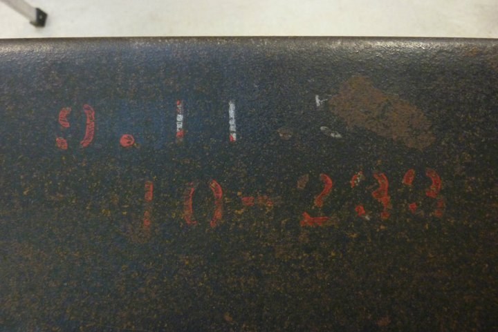 Found what looks to be a frame manufactures date too. 9.11.58. Hard to make out the last figure now though as thought I was removing more from the top of it and it disappeared instead. So parts so far are 50 years apart with the Grand Cherokee donor being made in 2008. Still hoping to pick up another donor made in 1948 for the other half of the frame and body work too if the guy will ever set a reasonable price.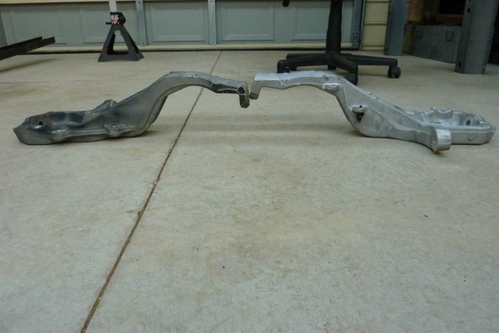 Removed the bent knuckle that took some of the impact from the Harley hitting it. Can see here just how much it bent compared to the new one on the right. Glad really that the cast aluminium knuckle bent rather than the cast steel lower or the forged upper wishbone did. Their mounts were unaffected too.  Both of these are sitting dead flat on the lower ball joint surface. Amazing how much change there is in vertical height as well. 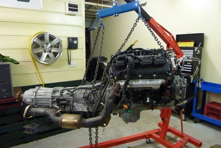 Removed the Hemi, trans and transfercase from the subframe so I can work on mounting the engine mounts further back in the sub frame so the axle centre line is centred in the wheel arch.  Moving the engine back meant that the oil filter would end up on top of my steering rack. Noticed that it was fitted to an angled adaptor so removed it. 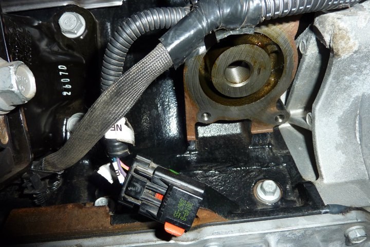 This left this behind but with nothing to screw the filter back on to. 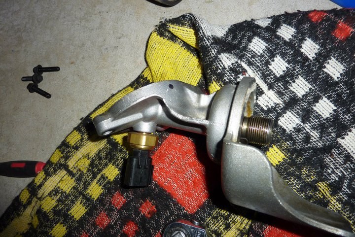 This is the adaptor with the threaded part for the oil filter and the oil pressure gauge sender.  The threaded section just simply unscrewed with an Allen key and installed into the block directly. 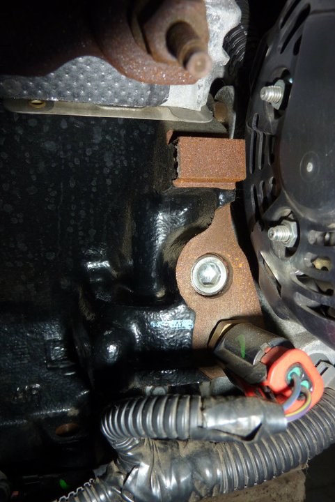 The adaptor also had the oil pressure gauge sender so had to find a new place for that. Noticed this plug above the oil temperature sender. 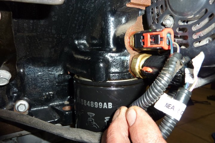 The oil pressure sensor was too big to fit into the upper hole, so swapped the oil temp sensor in there instead. The thread however on the oil pressure sender was too small and I didn't have an adaptor. So I drilled out the plug that was in the upper port originally and threaded it for the sensor and installed it that way.  Gives you a better idea of the sub frame that holds everything under the uni-bodied Grand Cherokee. Just held in place with four big bolts. I will be doing the same so I can bolt it under the Willys frame. Paint damage in the front corner is from the battery acid leaking on to it after battery was split in the impact with a tree after being hit by the Harley. 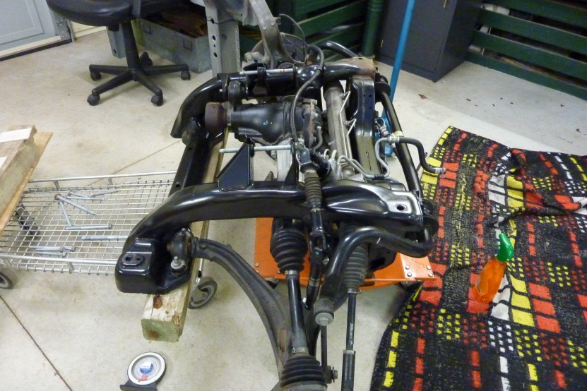 Just got to workout how I will make my new engine mounts once I move them 175mm back on this frame to centre the axle under the wheel arch. As the frame drops away steeply, cant just weld the old brackets back in place. Also going to end up over the top of the rear diff mount on the far side. Going to be fun setting it exactly right too as the mounts are 16mm lower on one side and 18 mm further across than the other side. Cant centre it otherwise the front driveshaft would hit the side of the transmission. They also have to have a 5.5 degree tilt to match the stock engine angle. 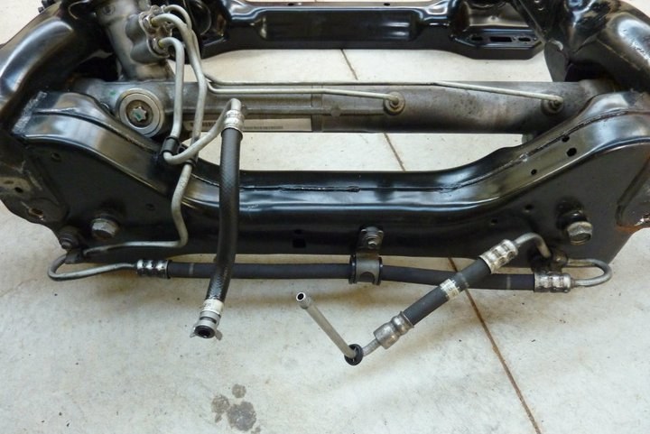 What's up with the way they routed the hose along the bottom of the cross member? Starts in the middle of the fan when in place, then goes across all the way to one side, then the other side, back part of the way and then over the cross member before entering the steering rack! I take it is something left over from a LHD to RHD design change? Can't see any other reason for it. 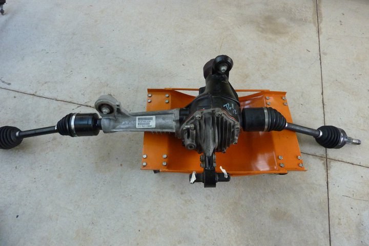 Taken the front diff out. Nice finned alloy cover and axle housing. 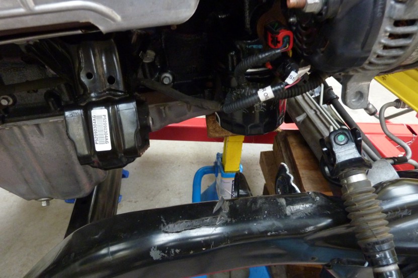 Got a nice alloy oil pan on the engine too standard. If you can see it after it is installed, might have to give it a polish! 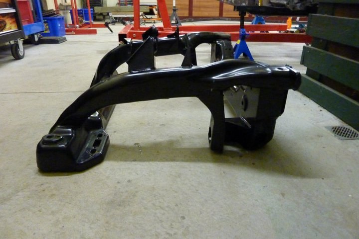 Here is the sub frame stripped bare. 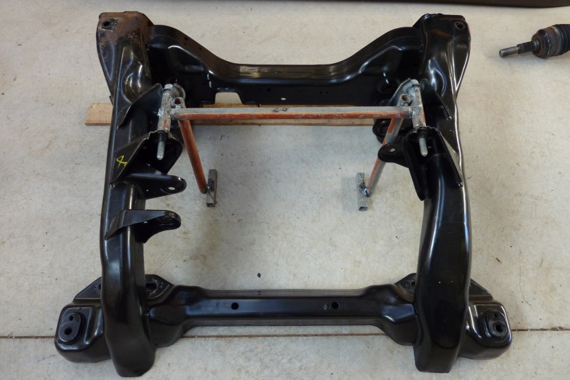 Before I removed the engine mounts, I made up this little jig to make it easier to setup the new ones. They tilt 5.5 degrees back and are different heights left to right to match the mounts on the block, so felt this was the way to go. Removed the engine mounts and mocked up the front cradle 175 mm further forward than it was before. Good news was that the oil filter change of position cleared the steering rack easily.  Even with the steering shaft roughly in place, there is still plenty of clearance around the oil filter.  The only thing I ran into was making sure the left engine mount cleared the diff support bracket. 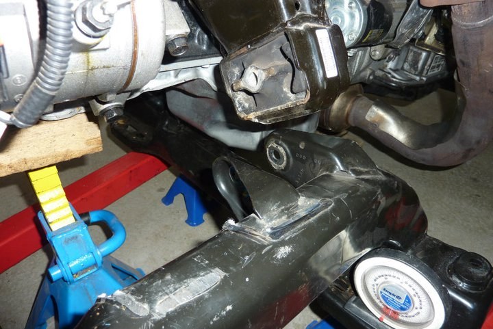 Got to make sure the new engine mount does not interfere with the front diff pinion support inside this bracket.  I set the floor and firewall up in place to make sure previous measurements were correct. They were exactly right but it was still nice to confirm before I go welding in the engine mounts in next. Also checked the radiator position to see how it would all fit within the engine bay. 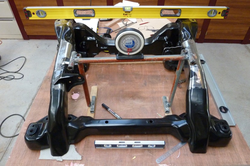 I setup my engine mount jig 175mm further back so the engine sits the same distance off the firewall but centres the front axle in the wheel wells. Had to raise it 3/4" above the what it was in the sub frame originally to clear the diff mount, but is still an 1" lower compared to the original floor height. Having it this far back will give much better front to rear weight balance for better handling as well. 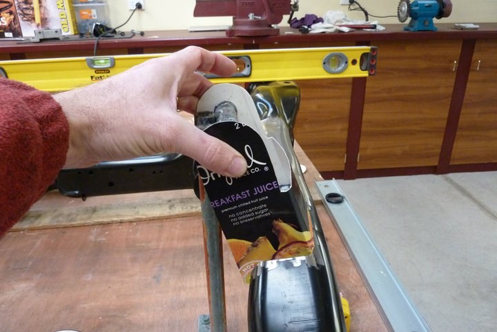 Good old OJ carton use to make a template for the new mounts. 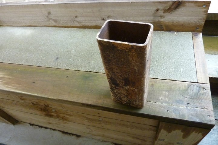 Knew it would come in handy one day. Brought this home when doing the structural steel work on the Hoppers Crossing College back in 1986! Bit overkill being 102x150x6 mm RHS ( 4"x6"x1/4" ) but had the perfect internal size to match the engine mounts on the block. Who would have thought that one end of this would be holding up a college building, and the other a HEMI! 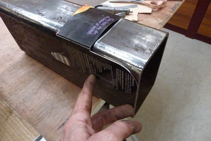 Clean up the tubing and placed my template over it. Made sure the bolt hole on each side matched perfectly. 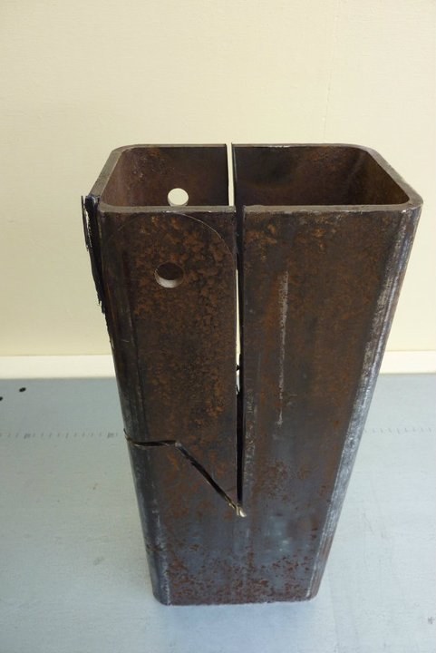 Don't own a oxy or a plasma, so out with the 9" grinder. 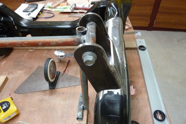 Fitting up nicely. 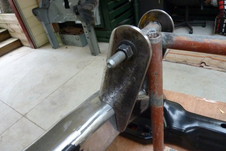 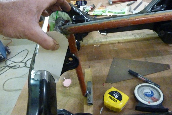 On to the other side. Healthy Choice meal box this time.  Just managed to squeeze in the other side from the same piece of RHS ( Rectangle Hollow Section ) tubing. 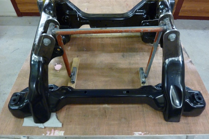 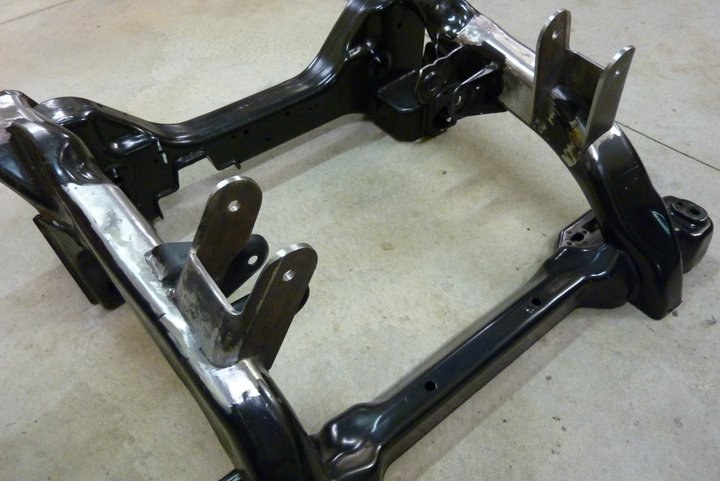  Fitted like a glove and just pushed the bolts through with my finger. 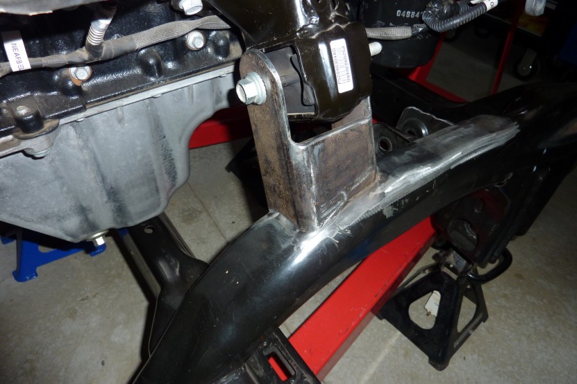 Other side. Haven't gone for anything fancy as impossible to see them once installed in the Willys. Strong and functional though. 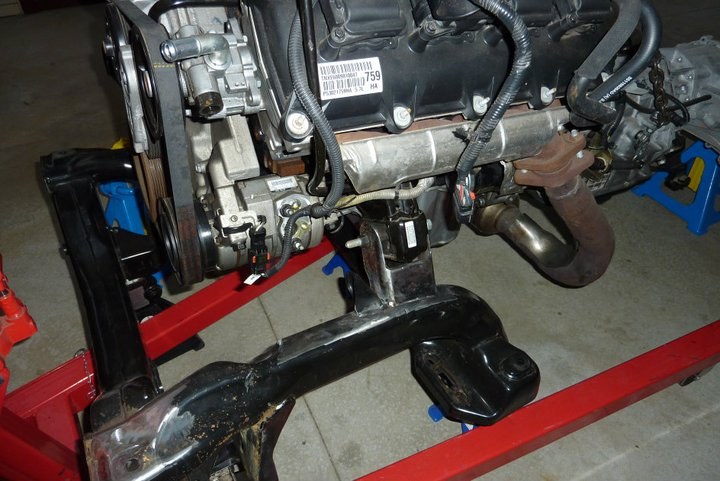 Sorry about getting carried away with the photos, but feel it is my first bit of construction on the project. 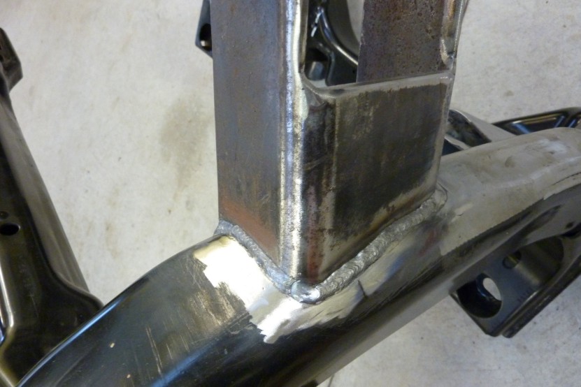 Had some leftover rods given to me when I bought the welder second hand 16 years ago. Hoped they would be still alright to weld the mounts in with.  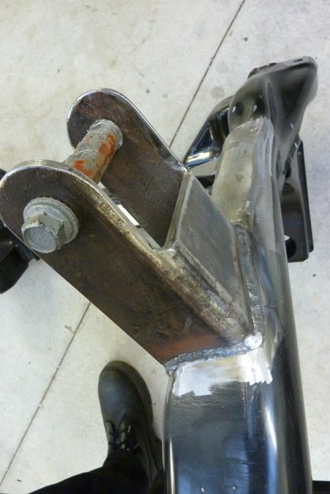 Not too bad for old rods I guess. 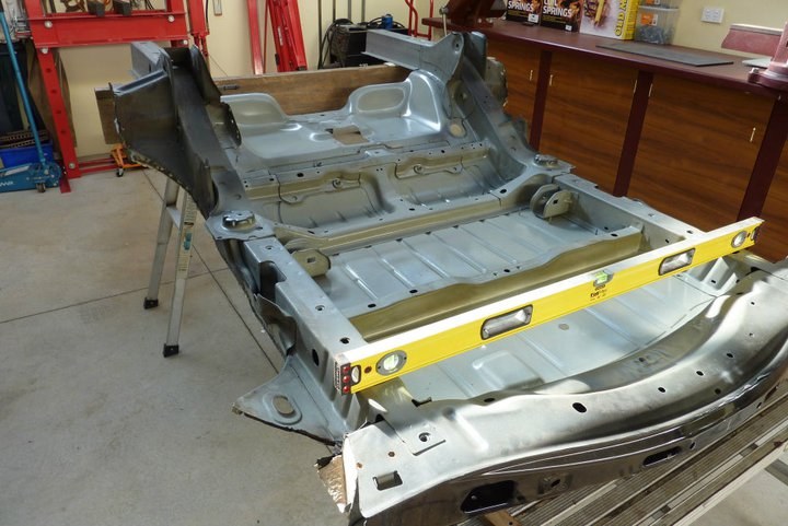 Back to stripping some parts again as still waiting on another Willys before I can really begin construction. Got a line on a 1950 cab that is on a HJ rolling chassis, but comes with a 1950 Willys complete rolling chassis and drivetrain plus a 1948 one as well! Trying to get him to sell me just the cab and 1948 rolling chassis as don't want the rest. Just cost too much to transport it otherwise as is 2000 km away. So it is on to removing the rear suspension mounts. Shown here upside down and ready to dismantle after taking all the measurements I need. 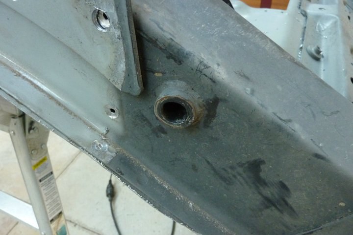 This bush is part of the upper control arm mount. So the weld needs to be cut away so it can be removed from this frame rail. 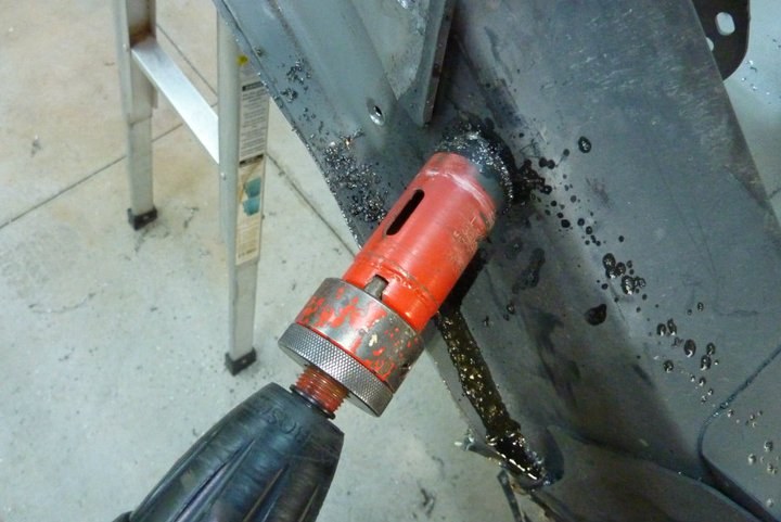 Easiest way I thought to remove the weld is to choose a hole saw with the same inside dimensions as the outer part of the bush. Didn't even need the pilot drill to be centred in something and cut through the weld easily. Just use a slow drill speed and some heavy oil, I used diff oil, to lubricate it.  So here is the upper mount off showing the bush I cut free with the hole saw that passed through the frame. The top mount is the lower control arm mount. All the suspension mounts are made with HSLC, (High Strength Low Carbon), steel. http://en.wikipedia.org/wiki/High-st...ow-alloy_steel 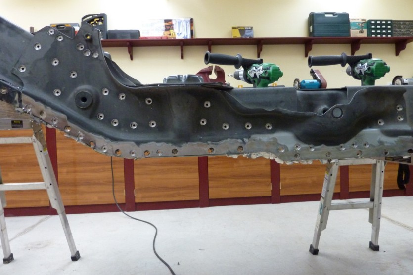 The photo shows how many spot welds I have to remove to get this reinforcement plate off. It supports the swaybar, coil and shock absorber mounts. You are looking at the Grand Cherokee donor rear frame section upside down.  Continually surprised how much effort they go to to stop noise transmission into the body. This a section of the frame that supports the rear shock absorber. 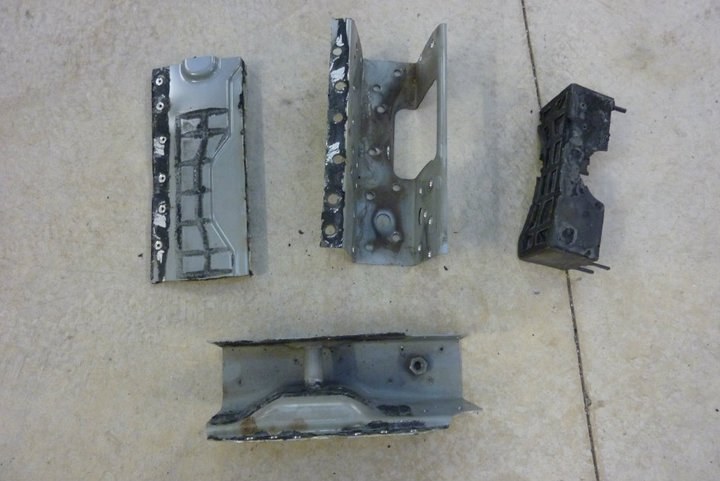 The rear shock mount broken down into pieces. Top left is part of the floor, outer frame rail, plastic noise absorbent material followed by the inner frame part that holds the inner part of the shock mount. 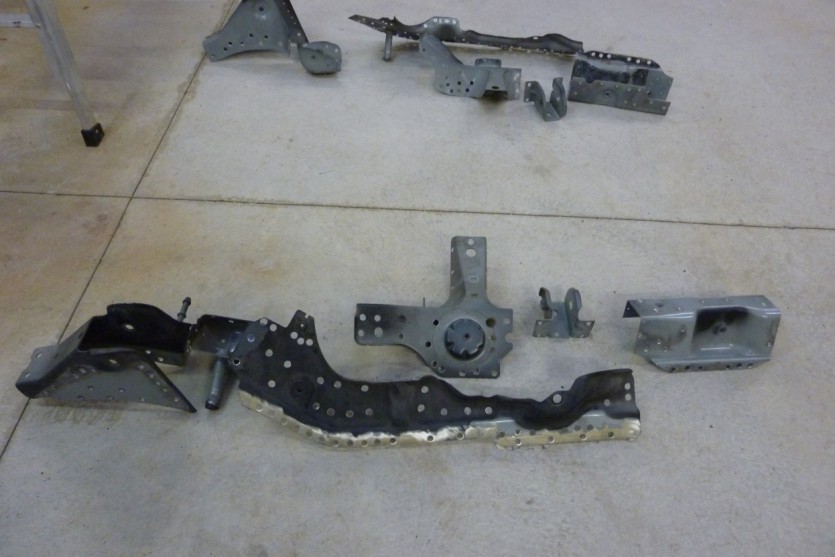 Starting from left to right along the back: Lower control arm mount, upper control arm mount, coil mount, panhard rod mount and shock mount. Across the front is the frame support for swaybar, coil and shock mounts Hoping to reuse all these on the Willys frame rails. Hard part is that the Willys frame is much narrower at 2" where these brackets are to fit over 3.5". Not sure the best way to make up the difference yet. 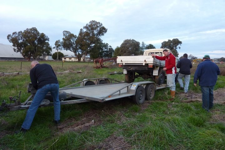 Well after 8.5 hours of driving we got to the place to pickup the new Willys. Unfortunately water had got into the front drums and locked both wheels and there was not enough traction to drag at back far enough. So muscled the winch hard to drag it up onto the trailer. 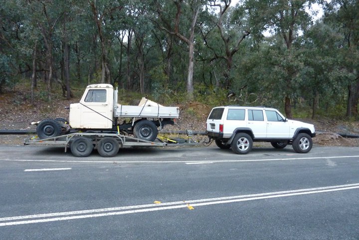 Our stop last night on the way home from picking up the new Willys pickup. Slept in the back or the XJ and got a good 8 hours sleep and not cold at all given it is the middle of winter right now. Jeep pulled like a train and never missed a beat. Could just leave the cruise control on a 100 and never slowed. Used way less fuel than I was expecting to which saved another $150 odd dollars off the expected cost.  Thought this was the best way getting it off due to the locked front drums. Just lifted it up with the crane until just clear of the deck. Then rolled it off the end, using the winch to control the speed, and onto a pair of wheel skates. 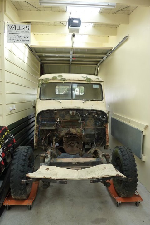 Just left it in the drive though area into the workshop overnight until the car trailer was returned in the morning. New sign looks good above it.
__________________
Marcus aka. Gojeep Victoria, Australia http://willyshotrod.com Invention is a combination of brains and materials. The more brains you use, the less materials you need. Last edited by Gojeep; 03-07-2020 at 07:10 AM.
|
|
#7
10-05-2014, 10:48 PM
|
||||
|
||||
|
Just finishing off a part that I was working on before picking up the new Willys. Hate to leave bits half done if I can avoid it.
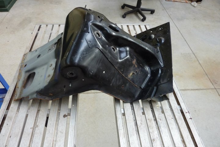 This is the mount for the upper wishbone as well as the coil over. It went from the Grand Cherokee uni-body frame to the inner guard. The right side of it was where the front guard bolted on.  As I cannot attach to the inner guard of the Willys due to having a separate frame, the two mounts will be braced across the engine bay to each other instead. So I cut off what was not needed but left an extra inch out from the coil over bolt area. This did make it look rather bad though with the pressed up part sticking out and open. Also the flared edge just terminates halfway along. 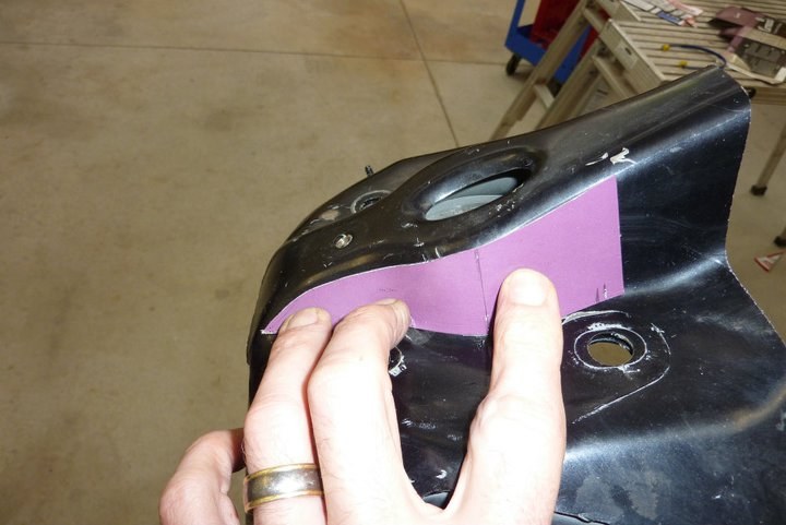 To improve the look of the pressed part that goes over the top of the shock pin, I decided the bring it down the same as the first half to close it up.  Flipped the pattern over making sure it was centred between the coil over bolt holes and at the same angle. 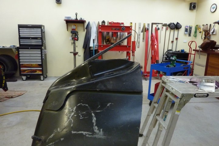 Using my new airsaw, cut the piece out 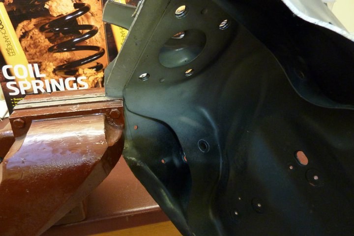 Continuing the flare along the edge was rather difficult as the HSLC steel has a 50% greater yield strength and requires 40% more force to form it. Even harder on the sections that were double thickness. So I clamped it in my vice and then pushed the hole mount to flare it bit by bit. Did this over the whole edge around three times to get it where it matched the factory flare. When going back over, made sure it was always between where I clamped it last to make it smoother. Had to use a 18" shifter in some places too. 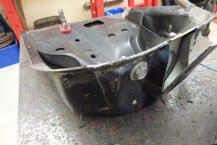 A small amount of hammer work was needed for the final finishing. Then arc welded the edge where it was double layered. 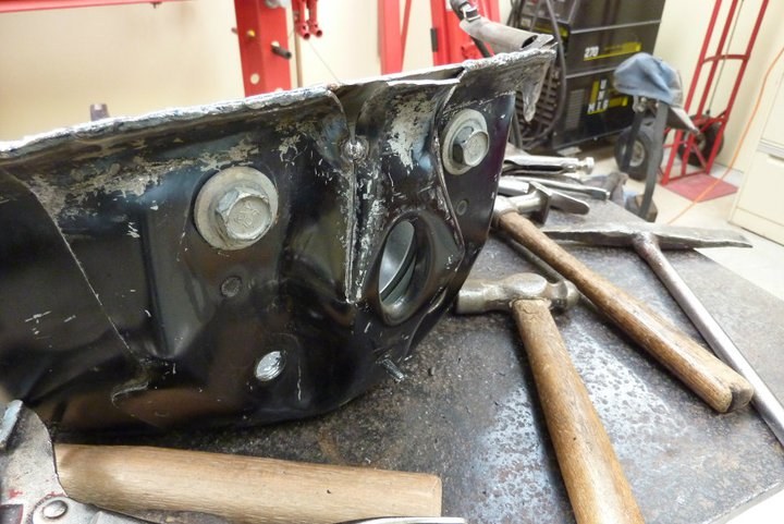 The top piece was pulled down and the end of it bent up a bit just using vice grips and hammering in the curve. 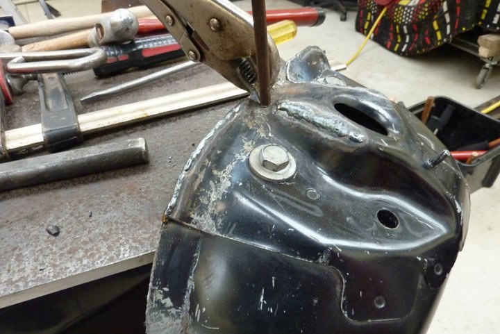 Welded the join closed except for the last bit which I could get the shape I was after yet as quite hard to move it cold. Hard to weld as the steel is galvanized and a bit thin for my arc welder, but very solid all the same. While it was still hot from the welding, I was able to get the bend I was after using a cold chisel and hammering across where I wanted the bend and then peening over the edge just using a rod.  Can see here how it looks much better with the flare continued all round and the open end closed up. 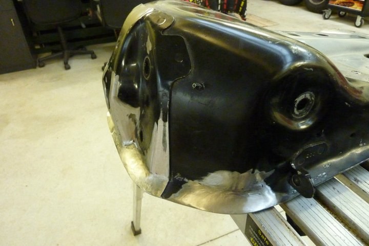 The flaring of the edge also stiffens up the whole mount considerably which is why the factory did the first part which was not part of the inner guard. 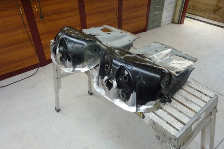 Another small piece done ready to be attached to the new 1948 Willys frame I just got on the weekend. Just needs to be stripped and cleaned yet though and meet my engineers approval! 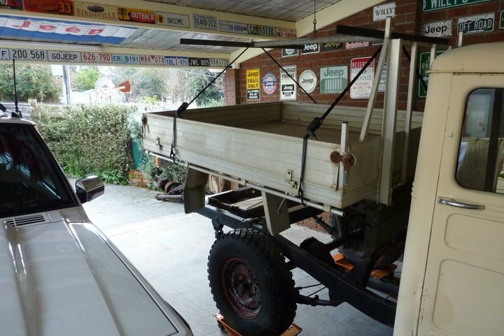 First thing to go was the aluminium tray which I sold off on eBay and brought the cost down on the Willys. 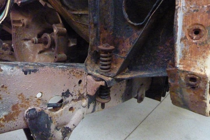 Unique body mounting system where all 4 corners are mounted with a coil above and below the chassis mount. Didn't stop this one from cracking anyway as these frames are so flexible. The other 58 model had the chassis mounts riveted on but ended up cracking the frame rail!  Rear wall is in rust free condition. This will be cut from this cab 7" wider than the section removed from the other cab to give me the wider cab and the small rear window I prefer. 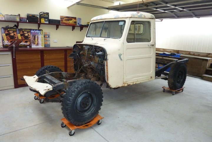 The middle section from this cowl will also be cut 7" wider than the section removed from the other cab. The doors will also be cut and added to the other cabs doors to make them 5.5" longer, (same percentage the cab is wider), for a stretch in over all cab length. Not going to bore you with the whole strip down of this one as it is no different to the first one I did.  Well another cab stripped and off the chassis. The 48 in the foreground is pretty much the same as the 58 behind it.  Main difference is the smaller rear window which I like so much more. 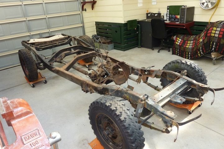 Next on the list is stripping this down to bare rails. Chassis rails look to be in better nick than the another one so intend to use this 48 frame for the build.
__________________
Marcus aka. Gojeep Victoria, Australia http://willyshotrod.com Invention is a combination of brains and materials. The more brains you use, the less materials you need. Last edited by Gojeep; 03-07-2020 at 07:13 AM.
|
|
#9
10-06-2014, 08:52 AM
|
|||
|
|||
|
Very detailed project. There's a lot of engineering going on. You must have been planning this out for a long time. This project's got it all. Great job.
I love those old Willys trucks. Looks like this will be a great project. Nothing like old school with new technology. Thanks for posting this. I'll be watching this build. Dave
__________________
Dave Deyton
|
|
#10
10-06-2014, 06:00 PM
|
||||
|
||||
 Just to show things are still moving along. Second frame has had everything removed that unbolts. Only rust so far is in one of the stiffening plates that I wont be needing anyway, so that is good.  Next step is to remove all suspension brackets, cross members and stiffening plates. 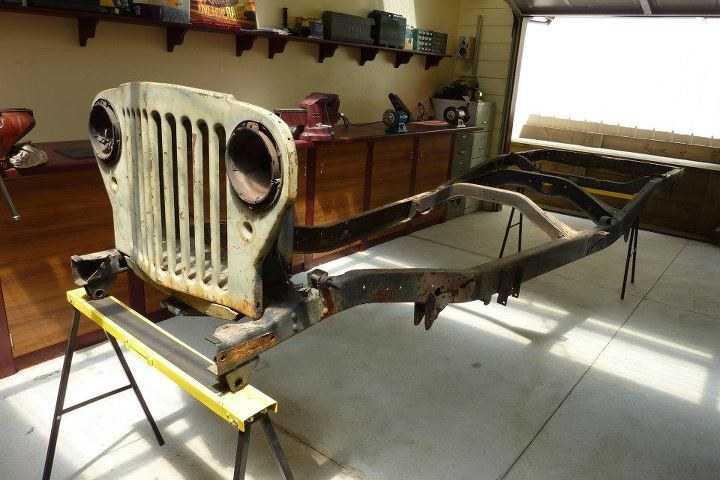 Been sitting like this for a couple of months but there is a little progress again. Been working on my other Jeep and went on holidays and then into hospital due to back injury. Just getting well enough now to do a bit of work on this once more, but nothing worth showing for a week or so yet. 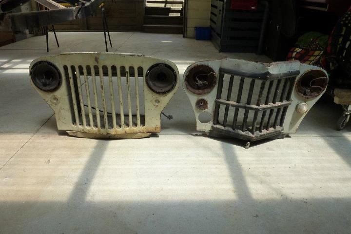 I have decided to run the 58 grille on the right instead of the 48 grille that matches the chassis year on the left. The reason is the I will be widening it and adding an extra grille slot to each side in the process. The 58 will end up with 10 slots just like the original 48 one. 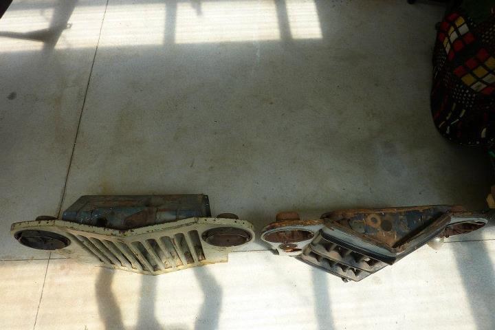 You can see why they call the later style 'pointy nose'. It also looks narrower due to the extra depth in the grille, but by the time I add two extra grille slots, will look similar to the flatter 48 on the left. 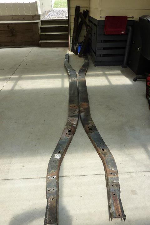 The de-construction has finally finished!!! Chassis now just a couple of rails. 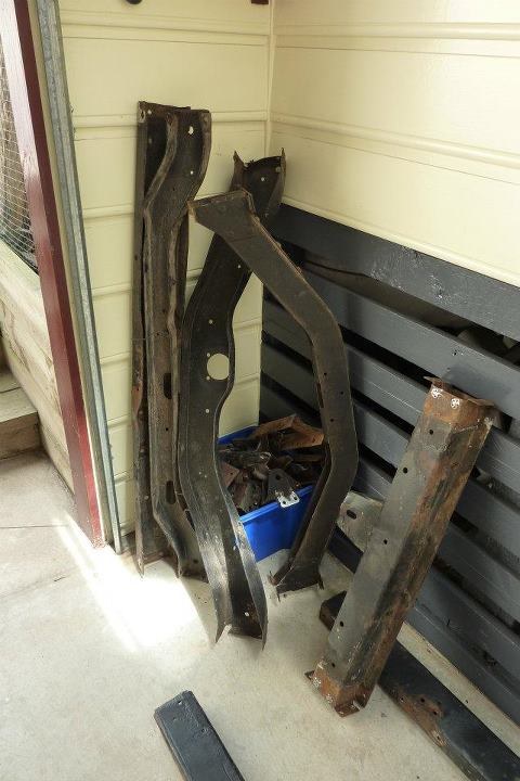 and some cross members and a box full of brackets. Now a lot of time needed to clean the rails and to inspect them. Done a couple of faces already and showing none of the frame cracking or large areas of rust pitting the 58 rails had so think I will be going with these instead. Who would have thought that the 10 year older 48 rails would be so much better. I have found 4 layers of paint on them though, so must have gotten better care over the years. The 58 rails had the original factory paint only. Got a start on the rails. 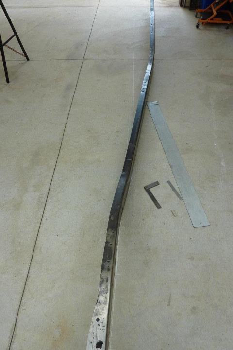 With the front of the frame where it needs to be over the chalk line, you can see how much the rear needs to come over. 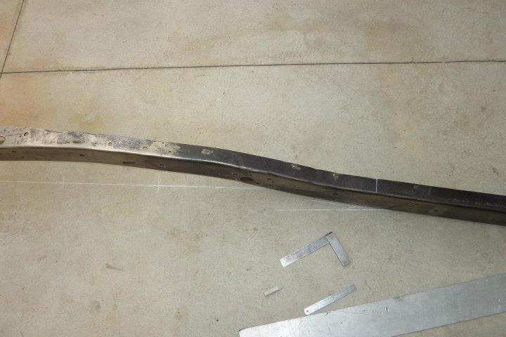 Leaving the first frame bend as is but adding a second bend a bit further along. This will allow me to run the rails parallel under the cab so I can fit the Grand Cherokee's fuel tank next to the driveshaft as it was installed on that vehicle. 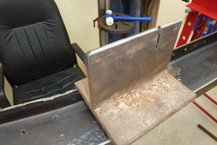 Quickly made up a primitive break to make the bend in the frame rail. Was originally a piece of I beam I got out of a scrap bin over 20 years ago! The slot will go over the one of the flanges as didn't want to cut the whole thing shorter in case I need the extra length later on. 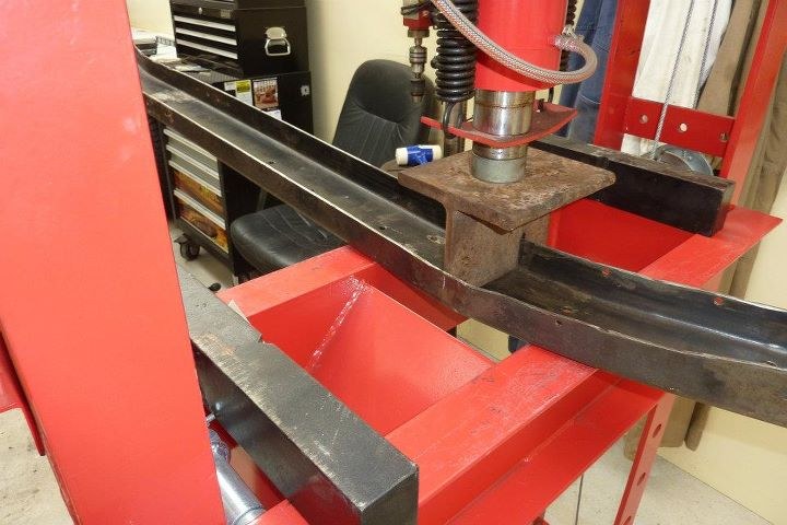 Centred the bend to be square to the middle part of the rail so I wouldn't get a twist in the rail like I already have from the factory bends! Also made sure the rail was exactly square to the press bed. 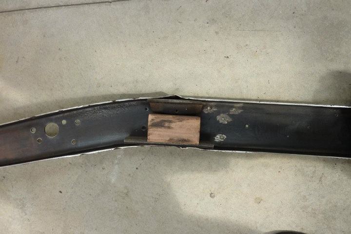 As expected there was some buckling due to the compression on the flanges. I over bent the rail a bit on purpose as expect the bend to straighten some when I remove these buckles. 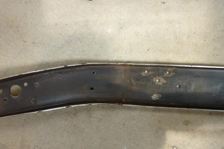 Some sledge and dolly work removed the buckles and ended up with just the angle I required. Had to use a short handled sledge due to these frame rails being 3/16" thick rather than 1/8" that you find on cars of the same era. 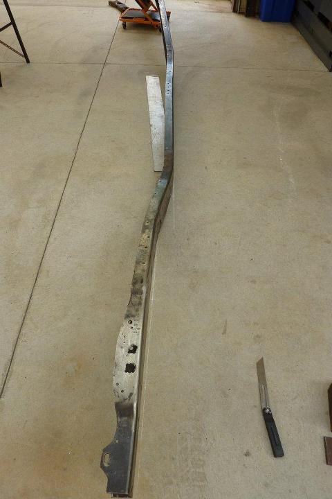 Can see now the frame follows the chalk line from the front to the end of the cab section. Camera angle makes it look slightly off, but that is due to the front being off the ground. 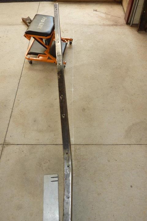 Next up will be the rear end. Needs the stock bend taken out to start with.  Worked it out to match the needed suspension pickup points as well. 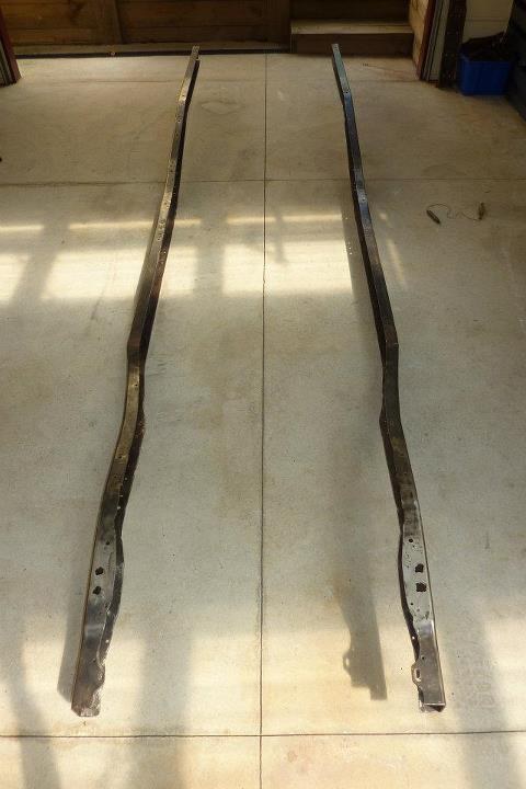 Both rails coming along. Next will be raising the rear above the axle 4" and the front 1.5" to get full upward suspension travel and not sit up high in the air. 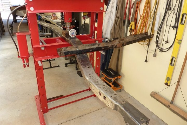 One of the rails had 2.5 degrees of twist in the end of the rail. So removed it by holding the rail in the press, bolting an old piece of channel to one of the existing holes in the frame where the twist was, then bouncing my whole body weight on the end of the channel. Came straight out. Simple but effective. 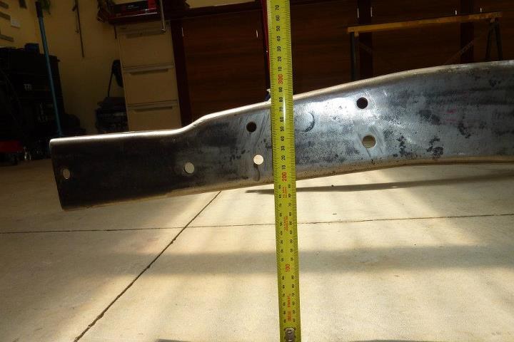 This is the point where the front of the Grands engine and suspension cradle will bolt on underneath. It needed to be 226mm, so need to raise the frame to match. 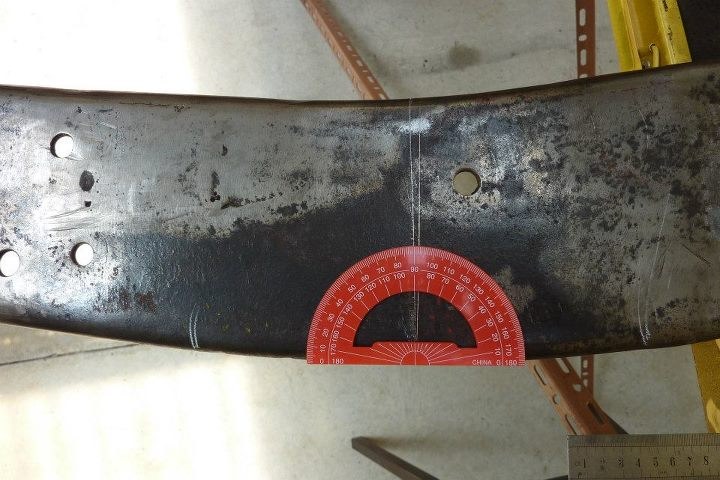 Used a triangle calculator, http://www.smex.net.au/Reference/TriangleCalc.htm to quickly workout how many degrees the bend, where it comes up from under the cab, needed to increase. Only needed just over 2 degrees which turned out to be a cutoff saw blade width. 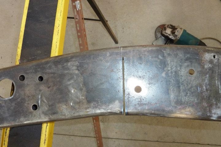 Line was scribed halfway in the curve and a right angle to it, then cut stopping an inch short of the flange. The reason I do it this way is that the bend in the lower flange will remain smoother and no obvious change will be seen. If you don't have a press, then can stop just before the flange and just pull the cut closed by hand. 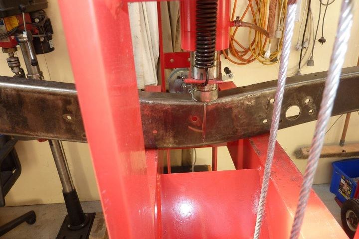 The cut was fully bevelled so full penetration will take place when it is welded back up. Then placed in the press to close the gap. Needed very little pressure and didn't distort the web of the channel. 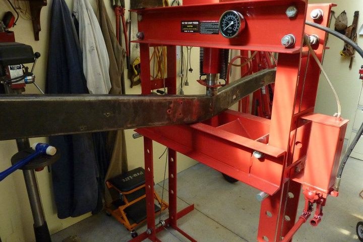 I tacked it while still in the press to stop it moving when the pressure was released. 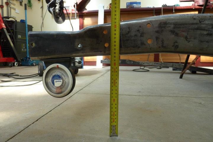 Got it right where I wanted. 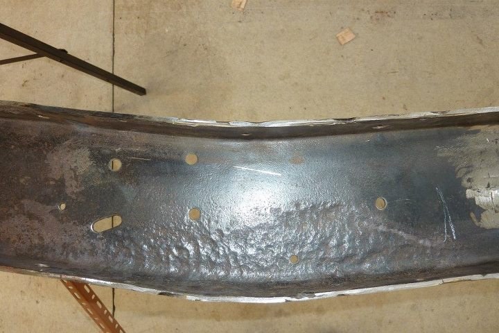 I have some rust repairs to do where the rail kicks up before the rear axle. Doesn't look too bad but there is a pin hole all the way through at one point. 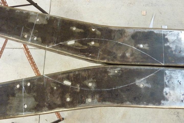 Both rails have it in the exact same spot as dirt gathered behind the cross member and stiffening plate that was riveted in here. Only the stiffening plate itself suffered rust as well, but going to be replaced with a full length boxing plate anyway. I will cut this away, then do the kick up in the same spot before welding in a replacement section of frame. OK, getting on with it a bit more.  Finally feel I'm in the construction phase now as got my first bottle of gas for my mig I bought three years ago. First weld out of the gun welding up the rail where it was bent upwards. Gave good penetration all the way through so not bad first up. Have put the old arc welder I have been using up until now in the corner. 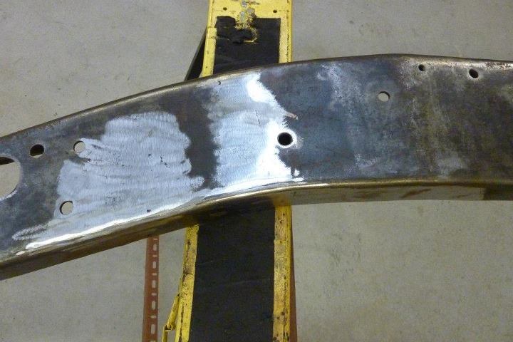 Cleaned up the weld a bit. Will do a better job later on. Just need to make fish plates for the back of the joins. 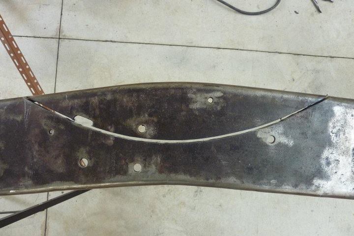 Cutting out the rusted section in the rear kick up now. 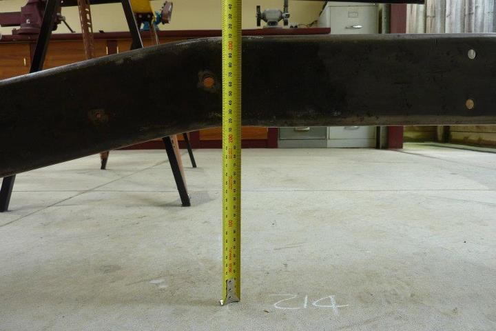 This is my starting height where the rail sits over the rear axle centreline. Looking at gaining 100mm or 4" to match the height it was stock on the Grand Cherokee. 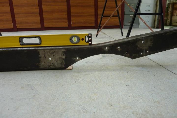 The first bend will be where the rust was cut away. So the flat section on the floor is what goes under the cab before kicking up over the axle.  Decided to just press the first bend seeing I already had so much cut away. Calculated I needed a 7.5* increase. Can already see the change in height. Now have to bend the rear section so it is parallel once again with the ground.  So cut out a 7.5* wedge out of the frame.  Worked out rather well 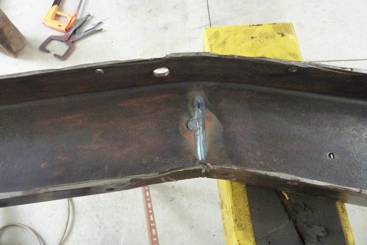 Showing penetration on the back side of the weld. The round bit off the the side was the old hole in the rail. 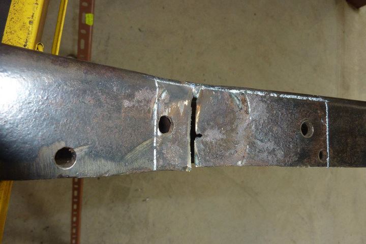 Left welding the flange as had rusted out above where the bump stop was.  Cut the section out and made it a little longer to remove some of the holes at the same time. 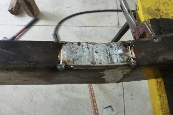 Cut a piece to fit and hammered in a matching curve. Brought back memories of my Blacksmith/Farriering days of my youth. 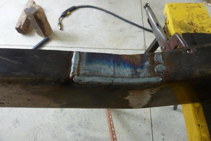 Getting used to the welder. First pass on the right was too hot so turned it down a touch for the other two passes. 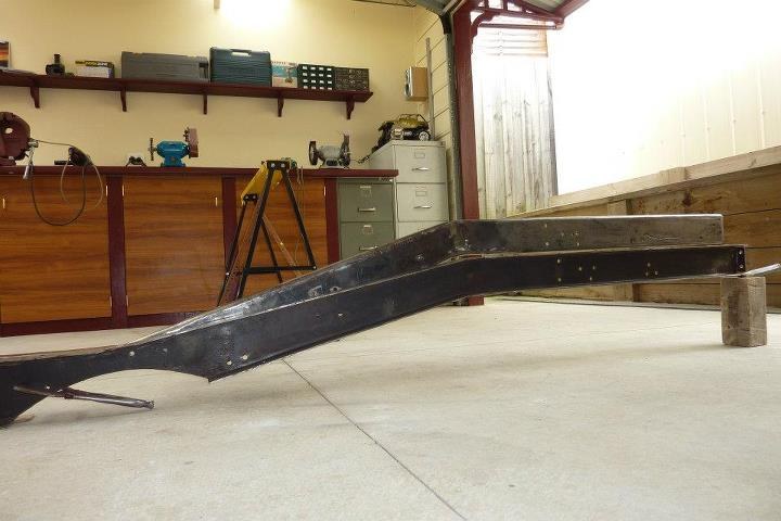 This gives a good representation of the changes I just made to the first rail placed behind the stock one. 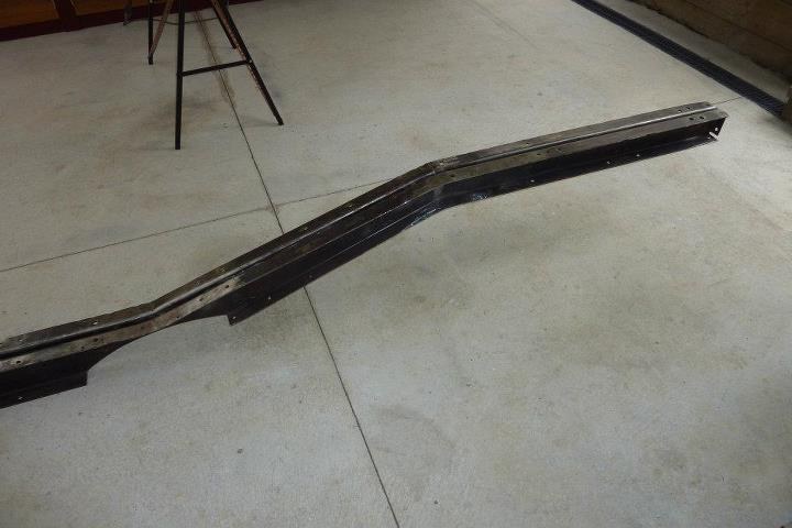 Both done.
__________________
Marcus aka. Gojeep Victoria, Australia http://willyshotrod.com Invention is a combination of brains and materials. The more brains you use, the less materials you need. Last edited by Gojeep; 03-07-2020 at 07:17 AM.
|
 |
| Thread Tools | Search this Thread |
| Display Modes | |
|
|


 Linear Mode

