
|
|
|
#1
 04-12-2015, 08:11 AM
|
||||
|
||||
|
Another task for the 55, the lower radiator baffle.
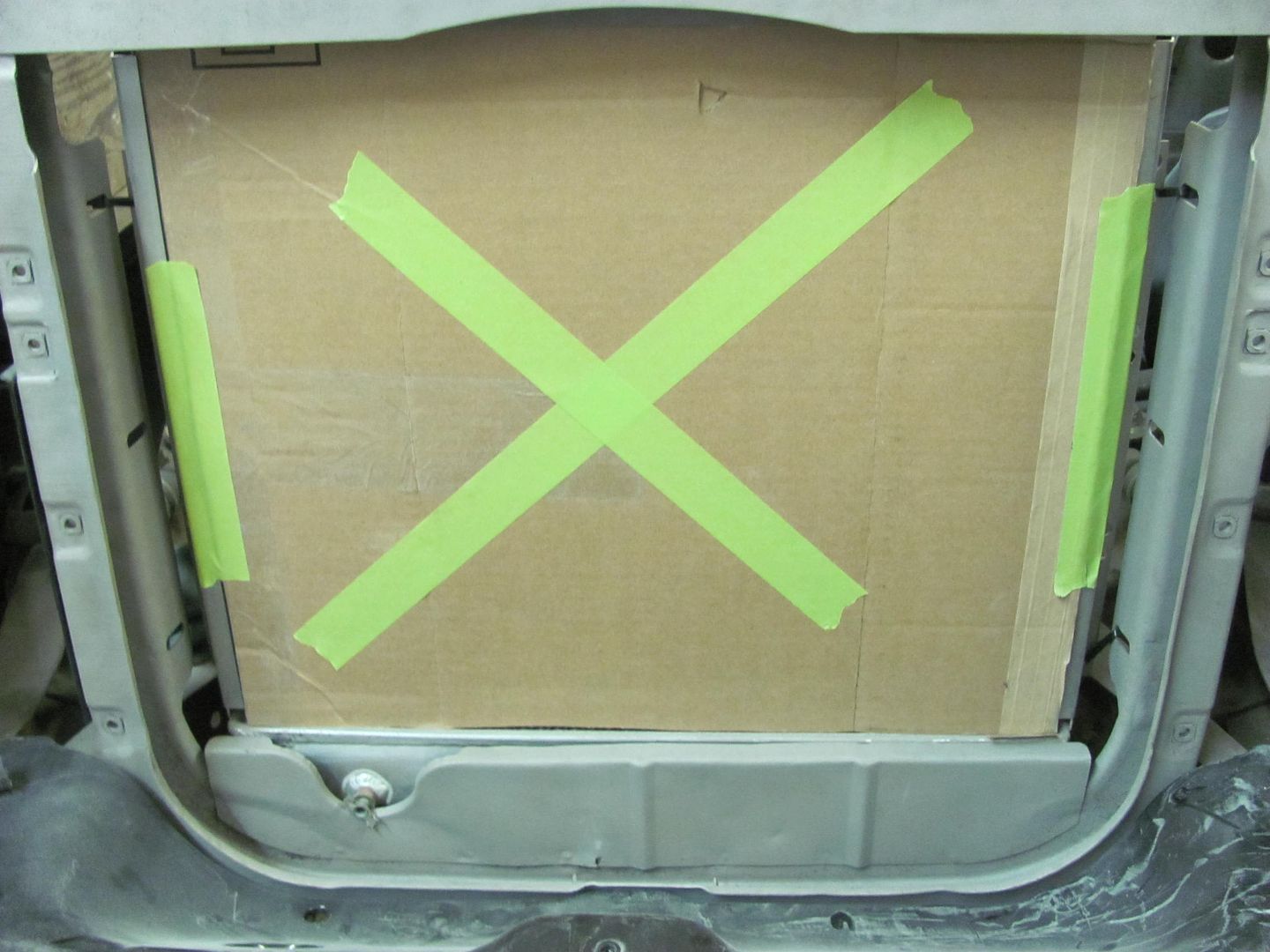 In addition to a few ripples and rust issues, this also has clearance issues with the radiator petcock drain. 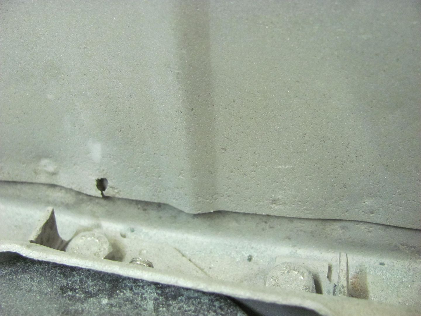 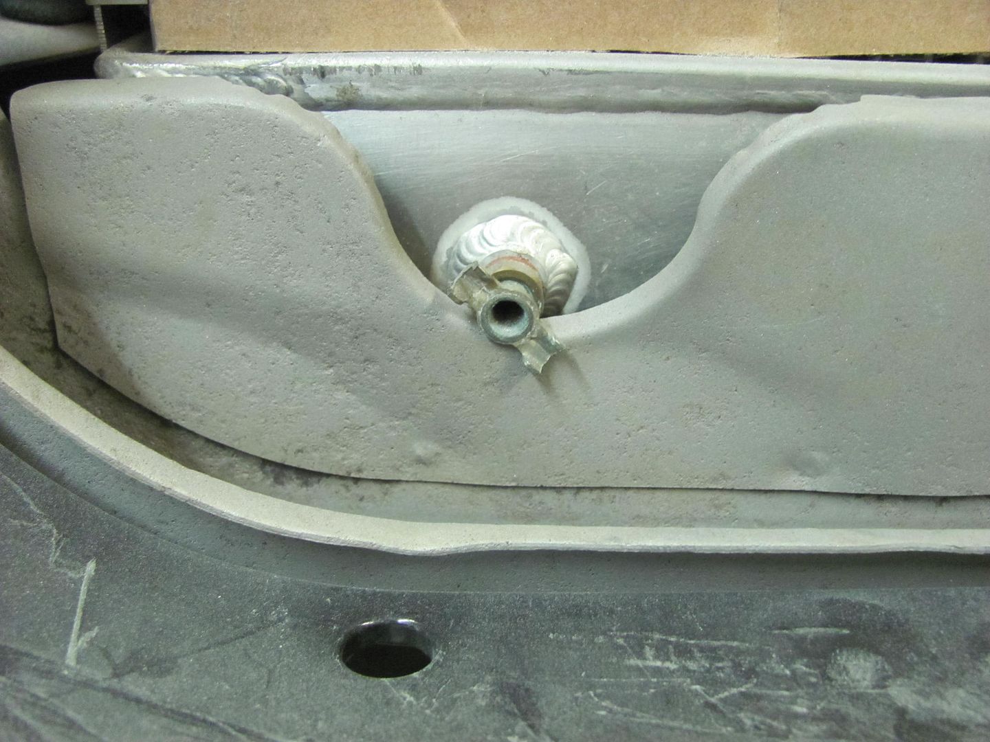 While this part is available in reproduction, it still would have the same clearance issue. So we may as well fix another of Chevrolet's designs... Checking the bead roller for the correct sized die showed that the Fasti didn't have quite the throat capacity. 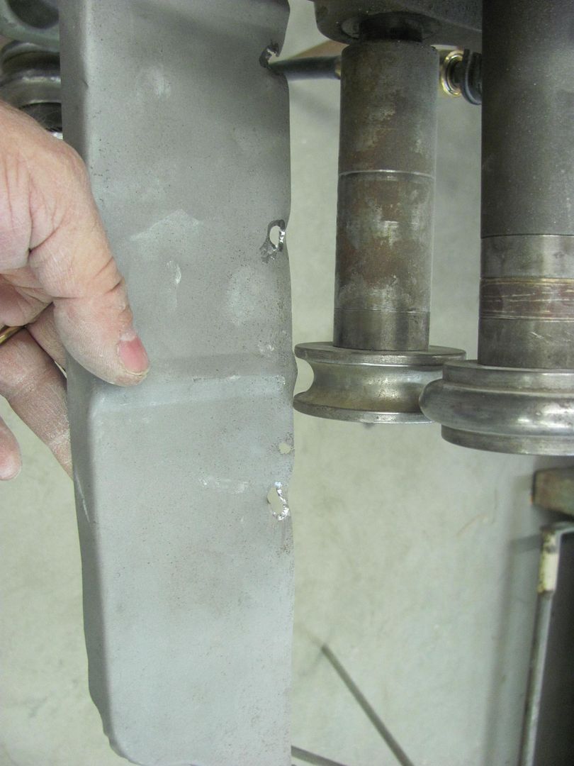 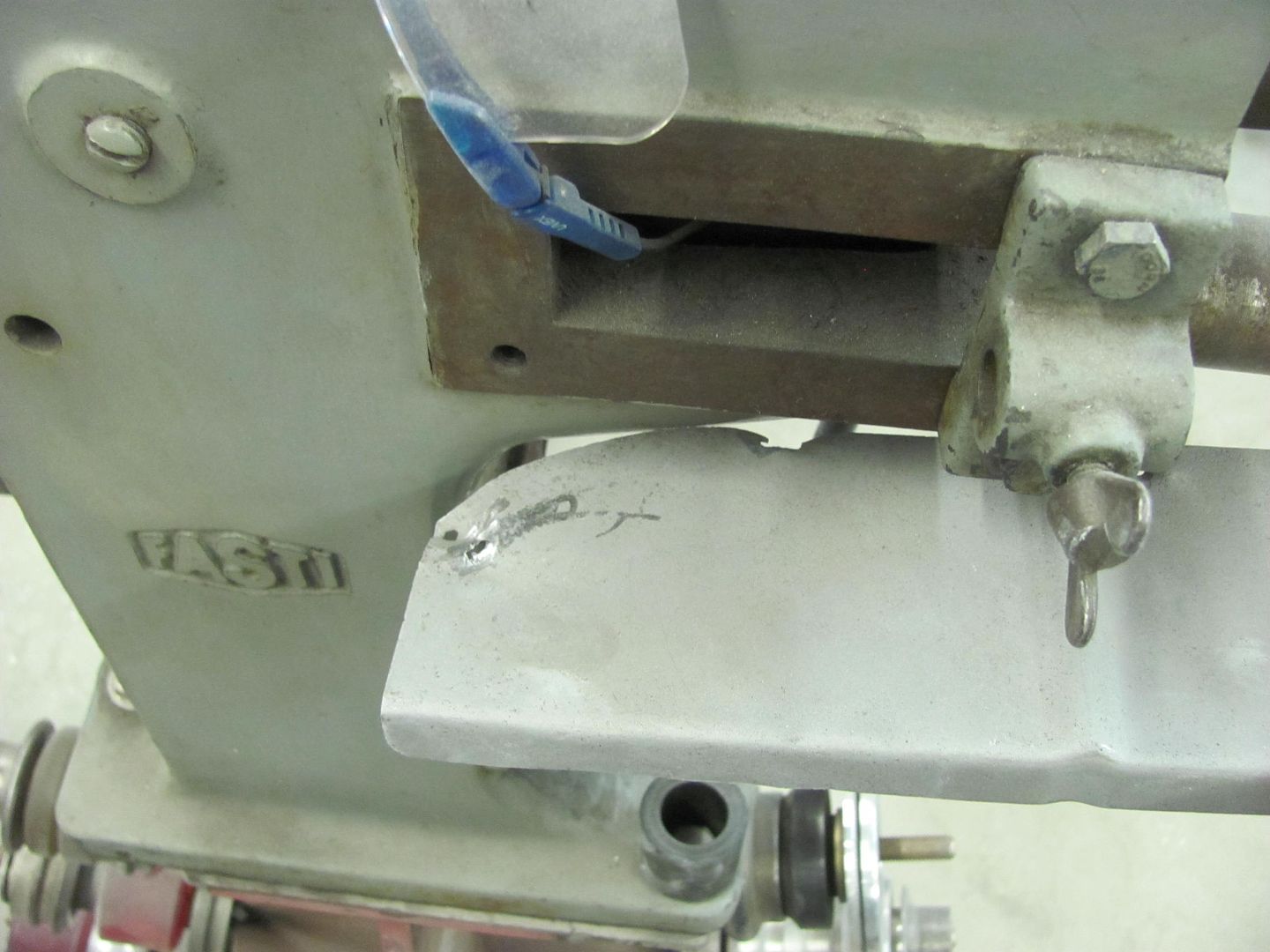 So the other machine with plenty of throat was the Lennox, so let's make some dies for it..... 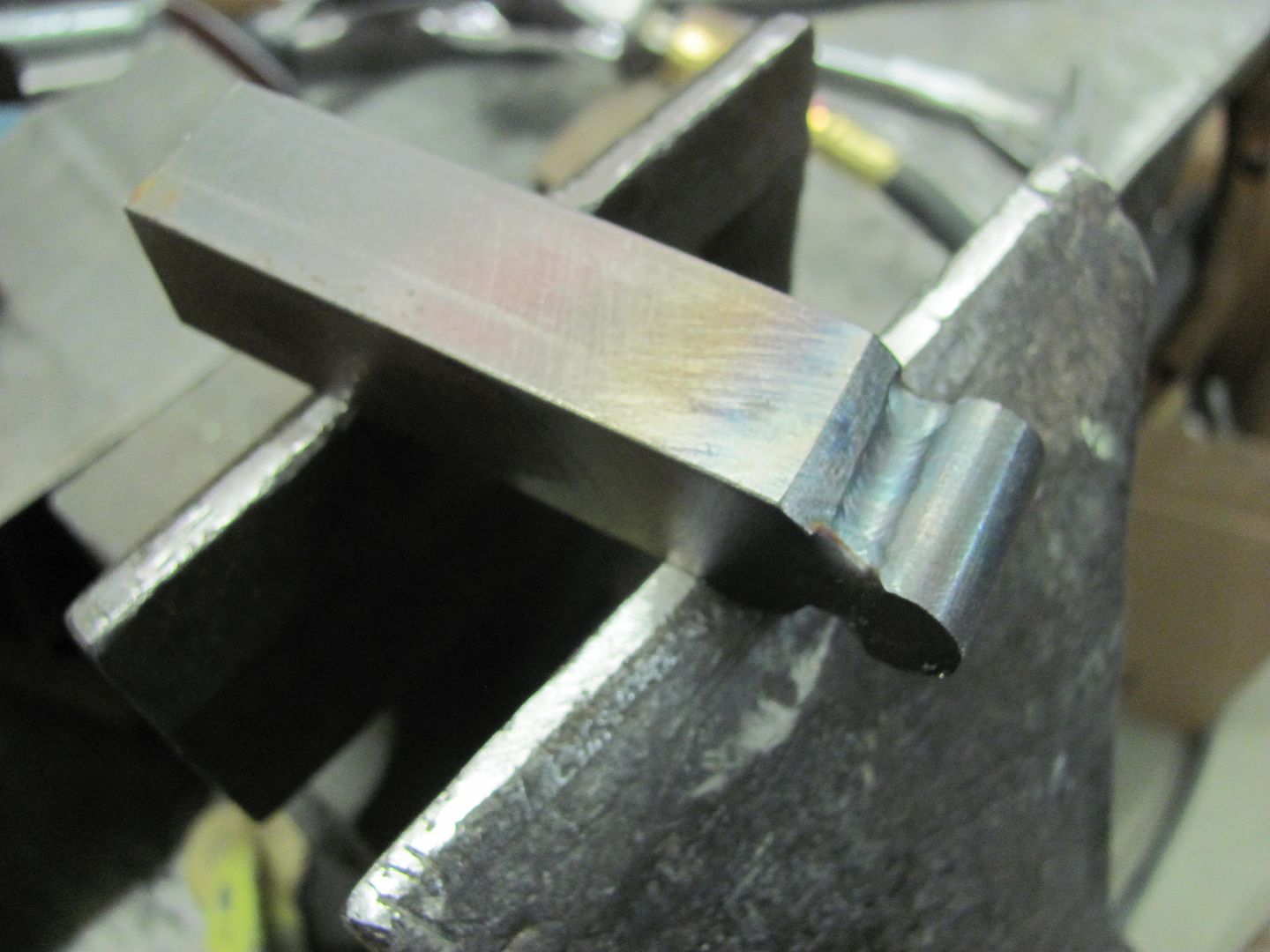 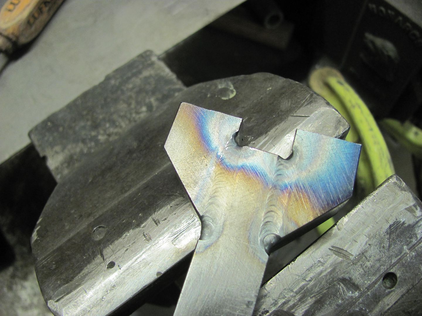 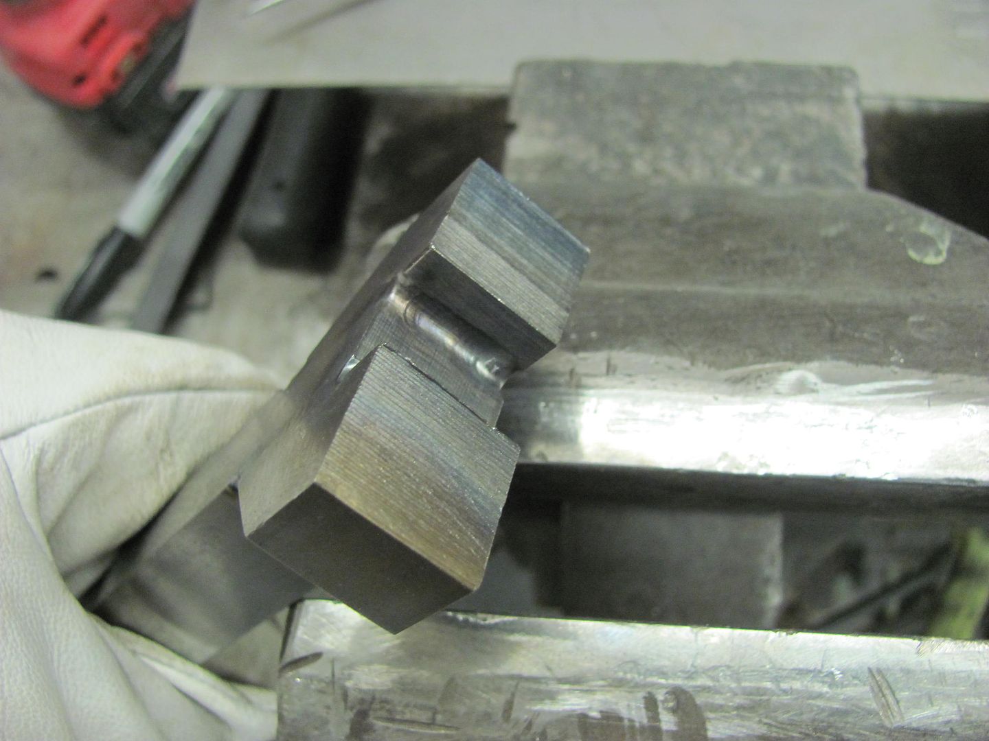 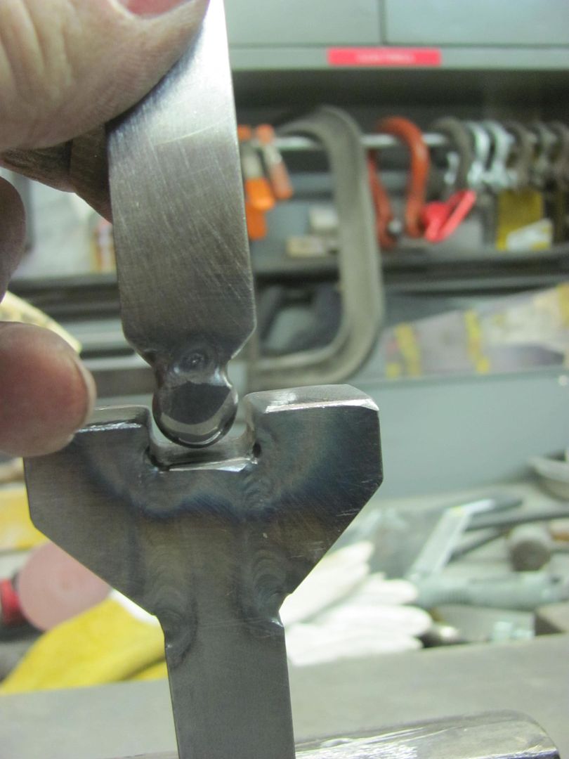 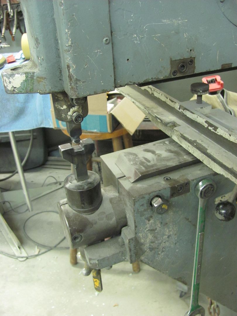 Pre-stretching the bead areas of the baffle... 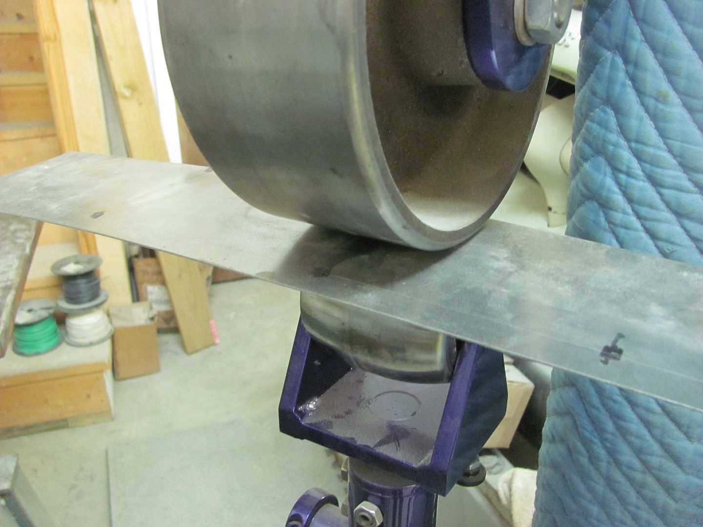  Adding the bead, using the backstop... 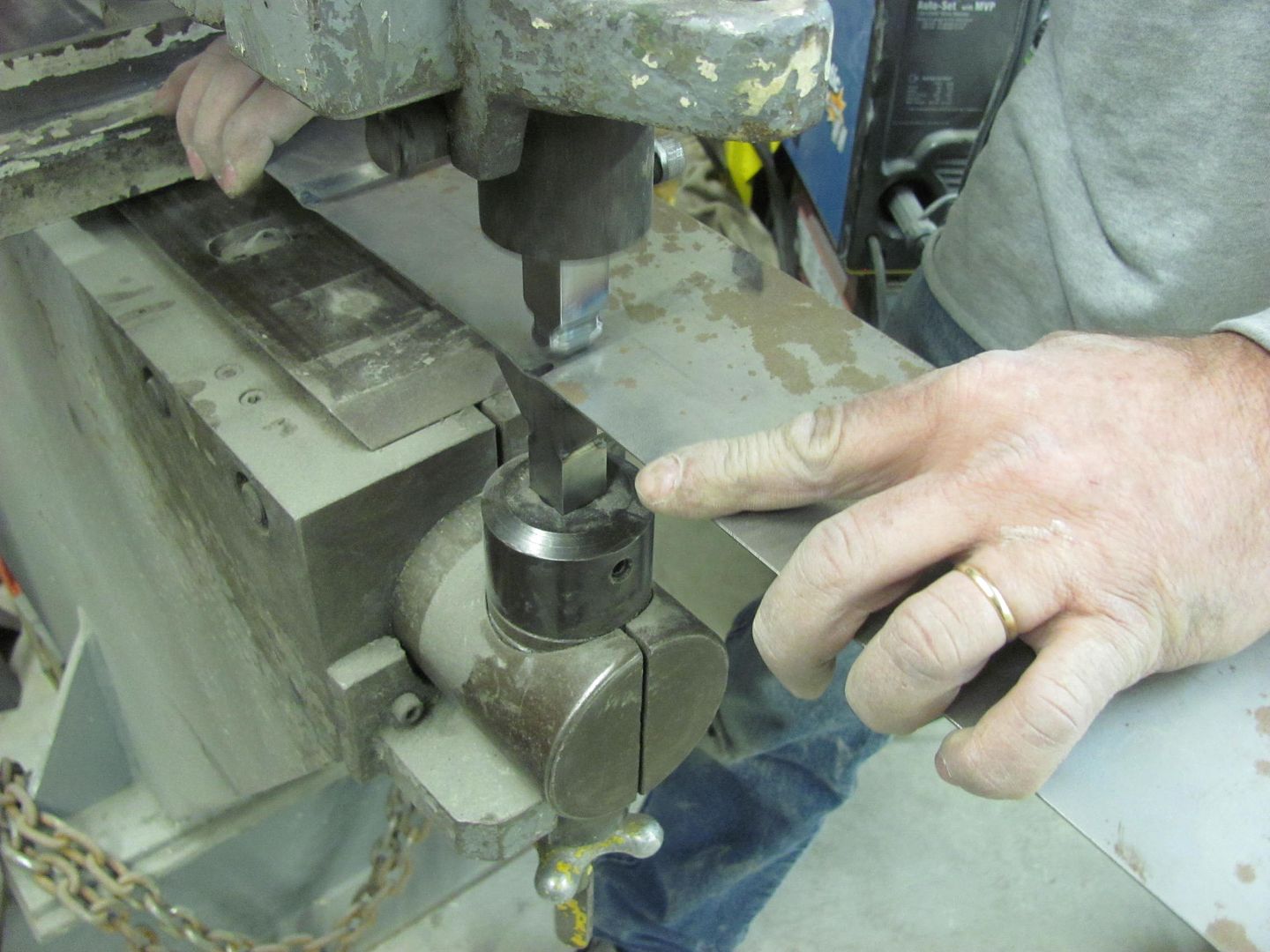  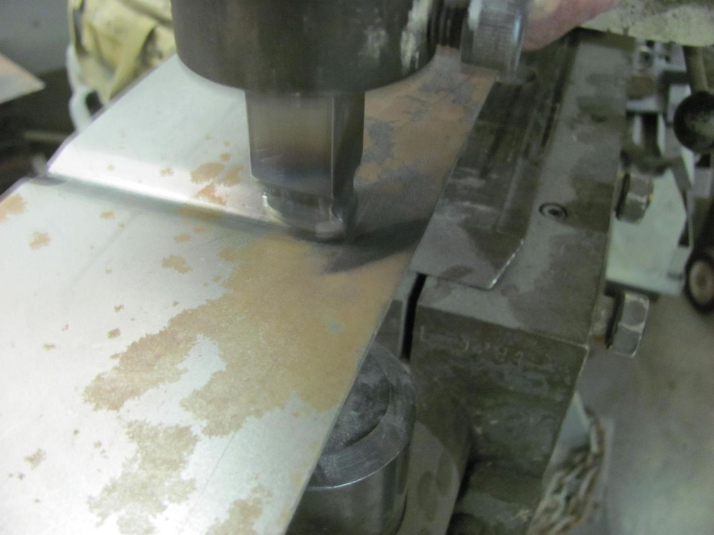 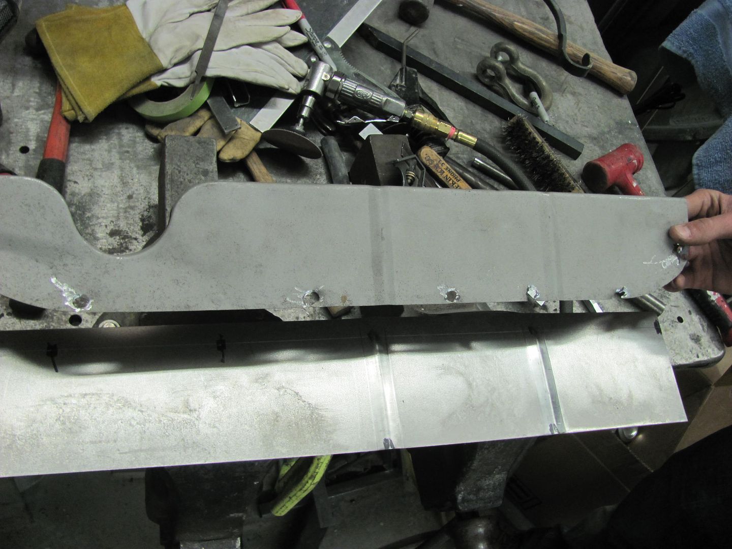 Laying out the petcock recess. This is about a 1/2" lower than the factory to alleviate the clearance issue.. 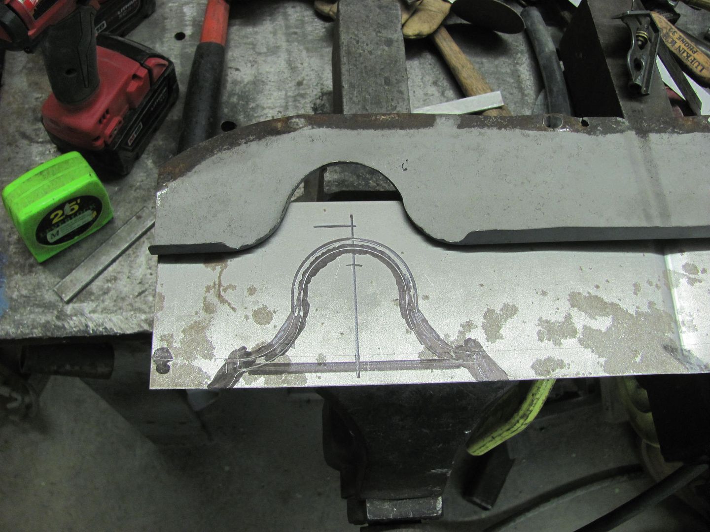 The tipping and skateboard wheels are used to "trace" the bend line to make any hammering a bit easier to locate the correct "edge"..... 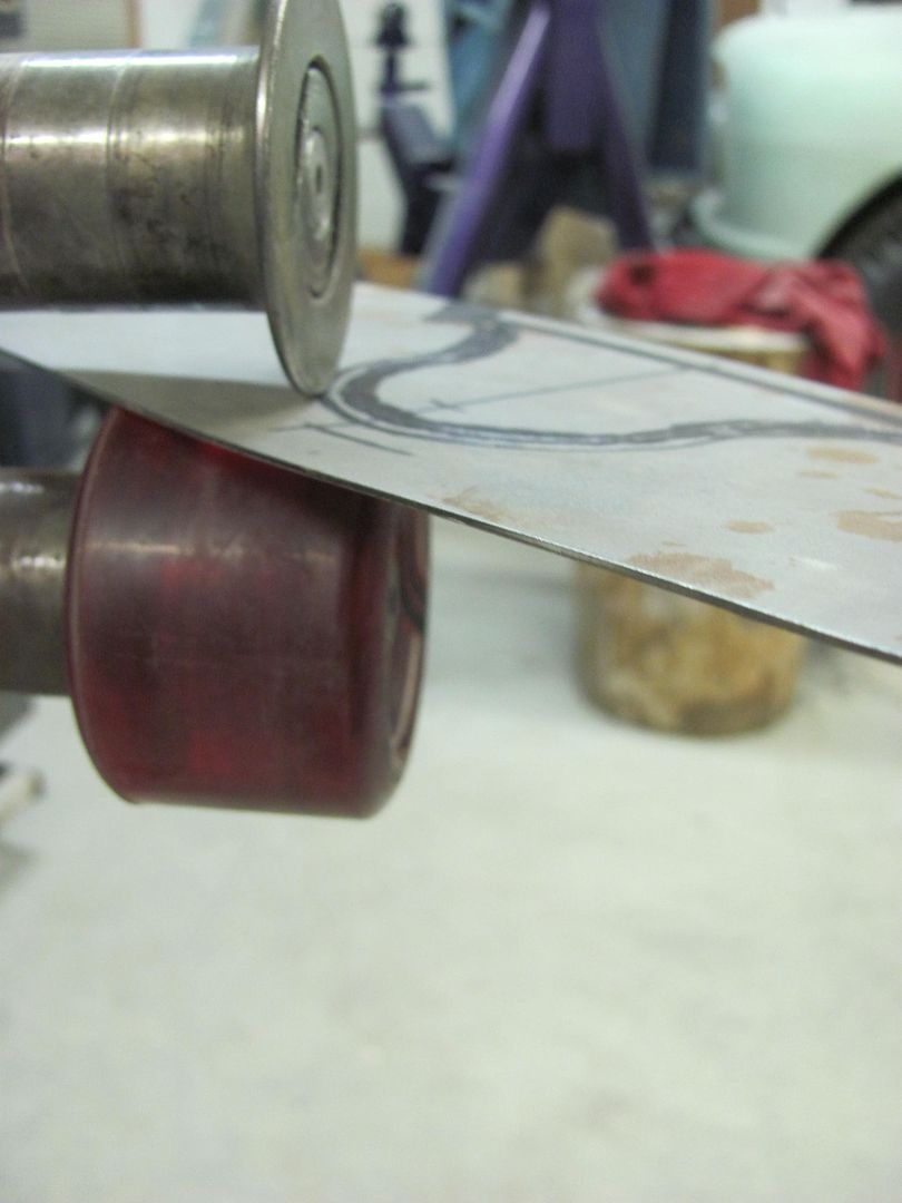 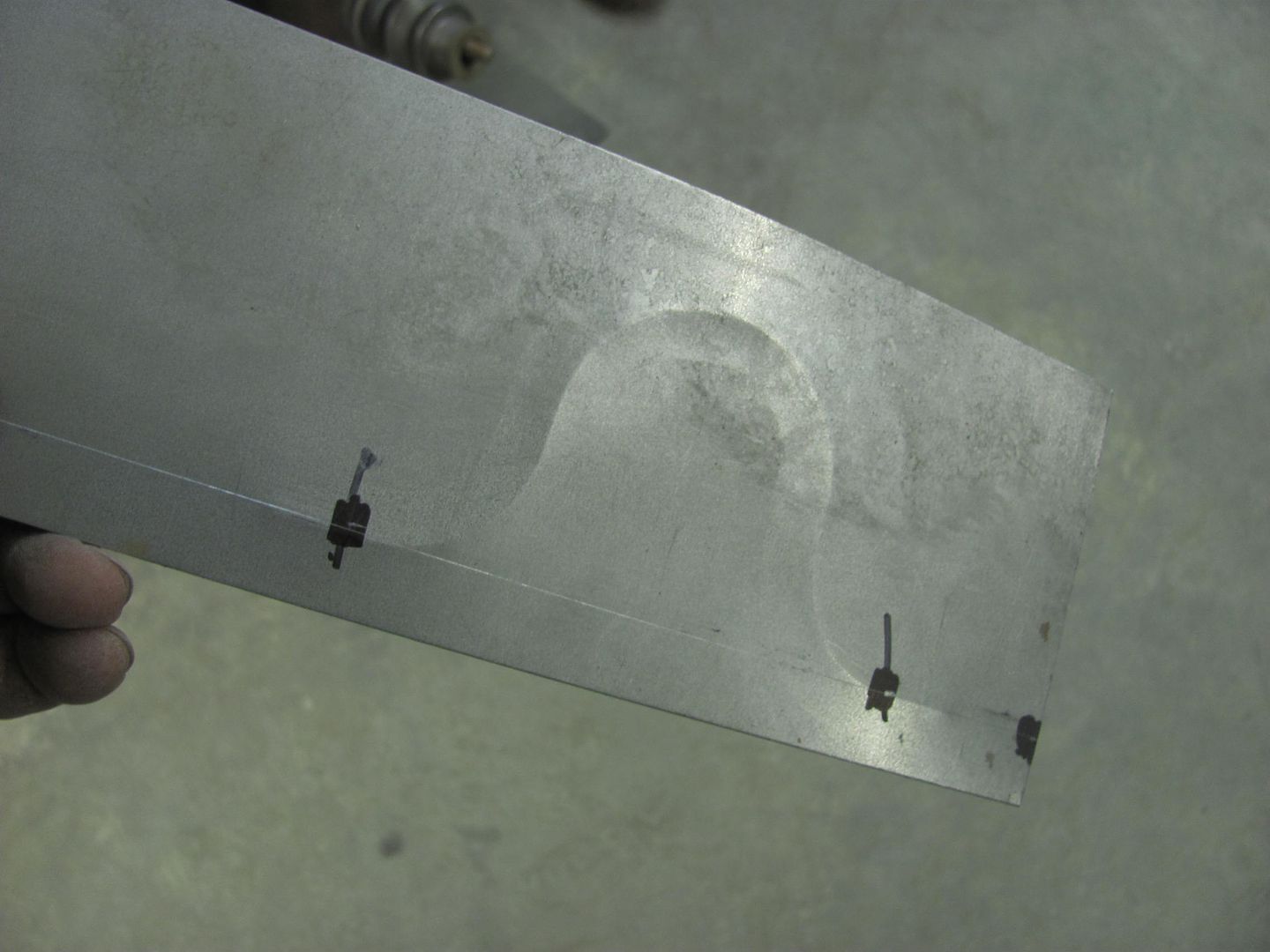 Relief trimmed, ready to make the folds.... 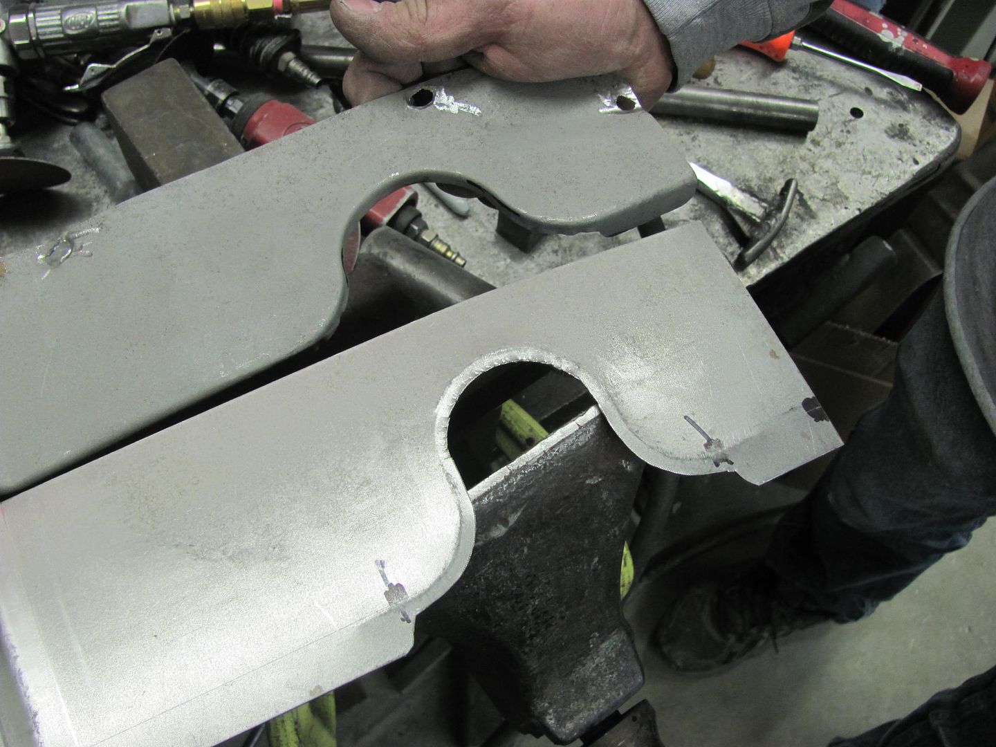 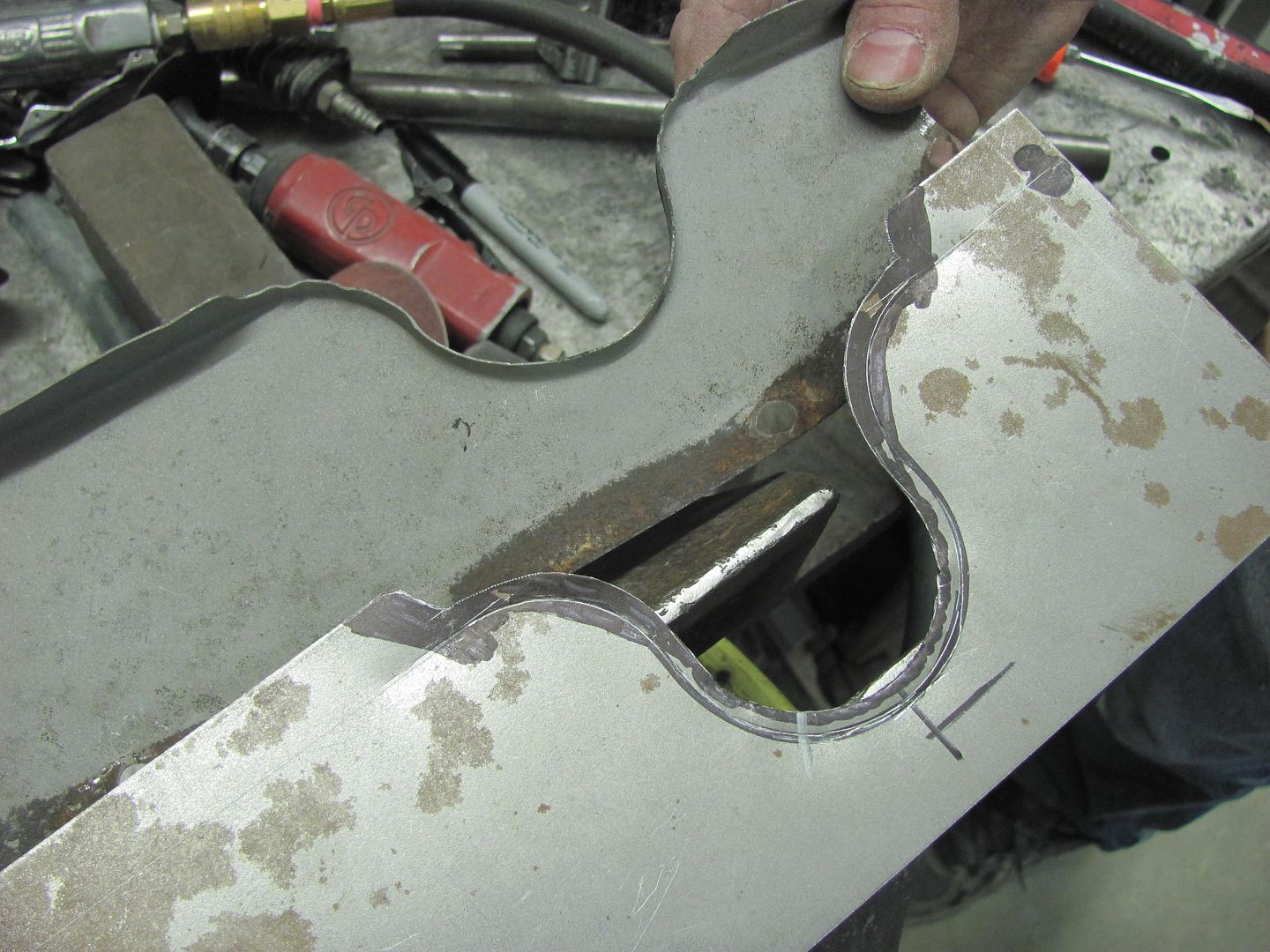
__________________
Robert Instagram @ mccartney_paint_and_custom McCartney Paint and Custom YouTube channel 
|
|
#2
04-12-2015, 08:21 AM
|
||||
|
||||
|
I missed getting a picture of the detail in bending the flange, but this should help to explain.. The bead was taken to the bend line and stopped.
Then the tipping die was used to form a partial bend, and then used some short die sections in the manual press brake to incrementally bend the flange over to a full 90*. The dies fit between the bead details so it didn't alter the bead. After the flange was complete the tooling shown here in the Lennox...... .....was rotated 90* so the flange could be inserted into the tooling from the front of the machine, and the "reverse" bead was formed by simply pulling down the handle to depress the punch manually with motor turned off. Using a 2" diameter round, seen clamped in the vise, the recess flange was hammered to form the perimeter lip..  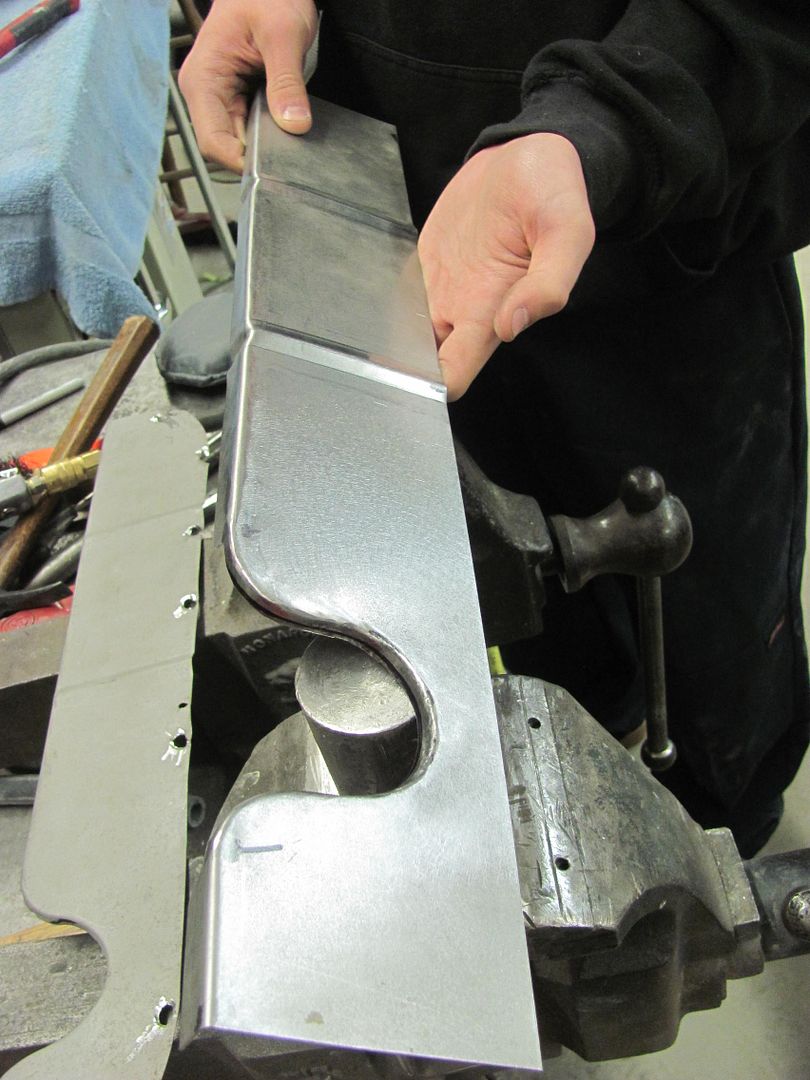 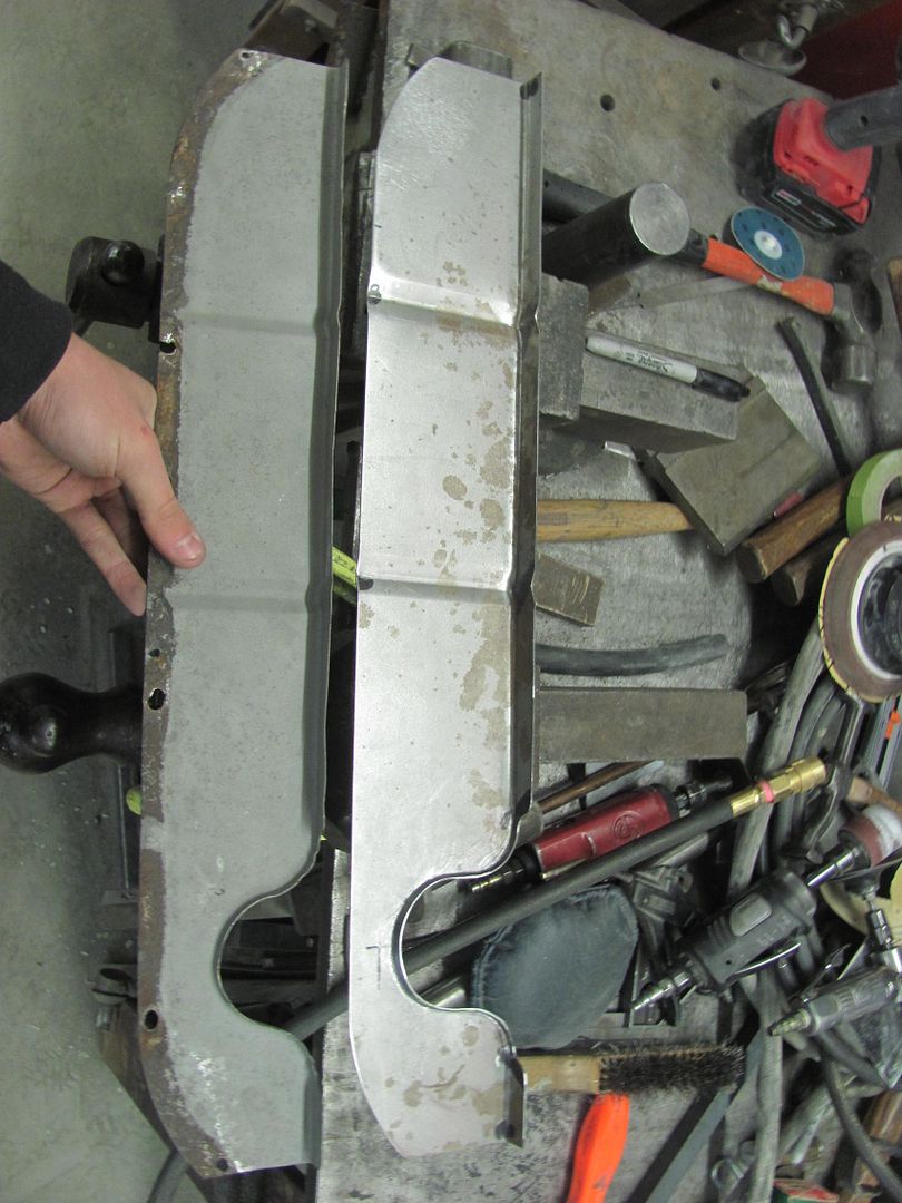 Test fitted... 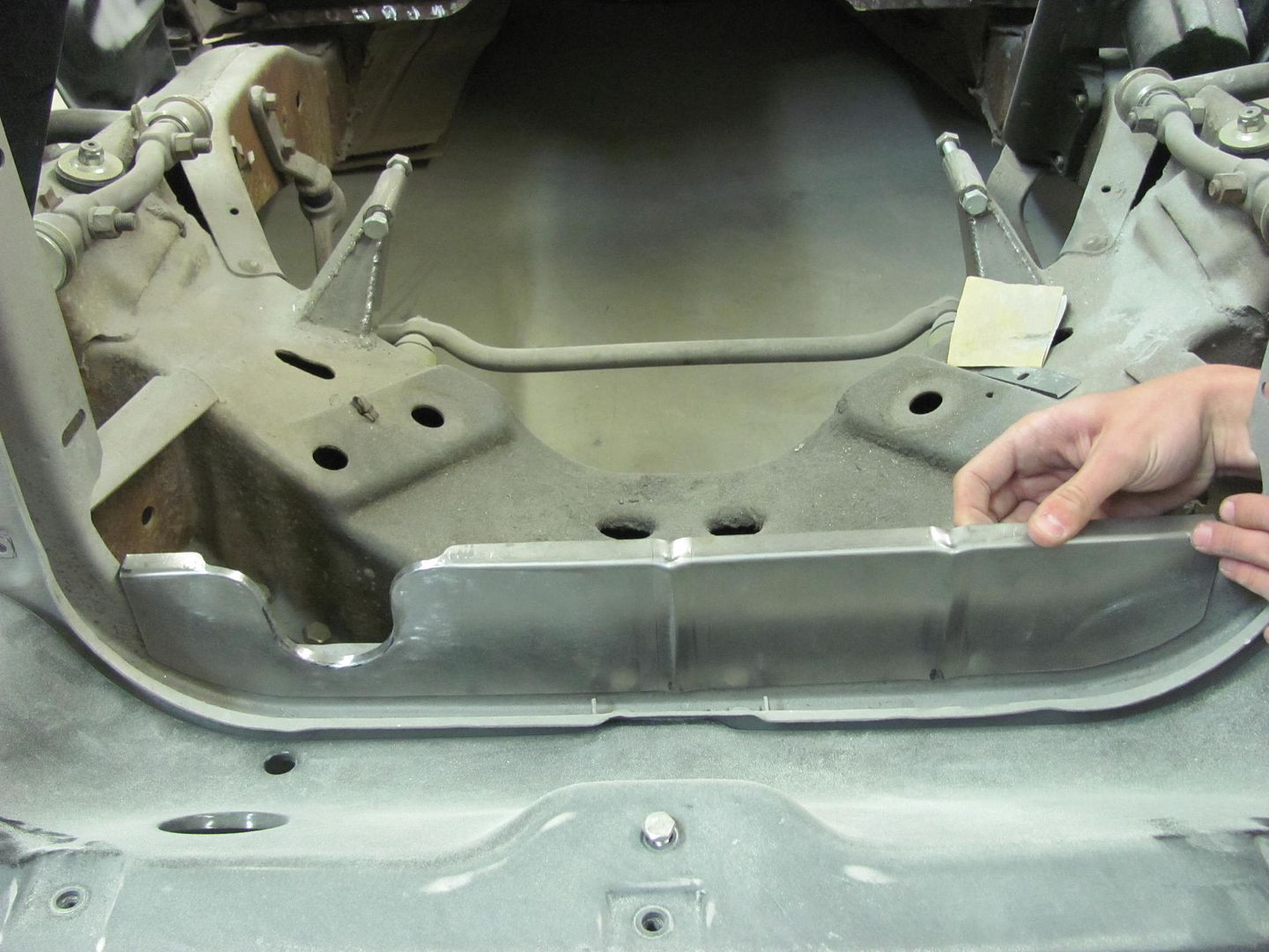 Media blasted, ready to install.... 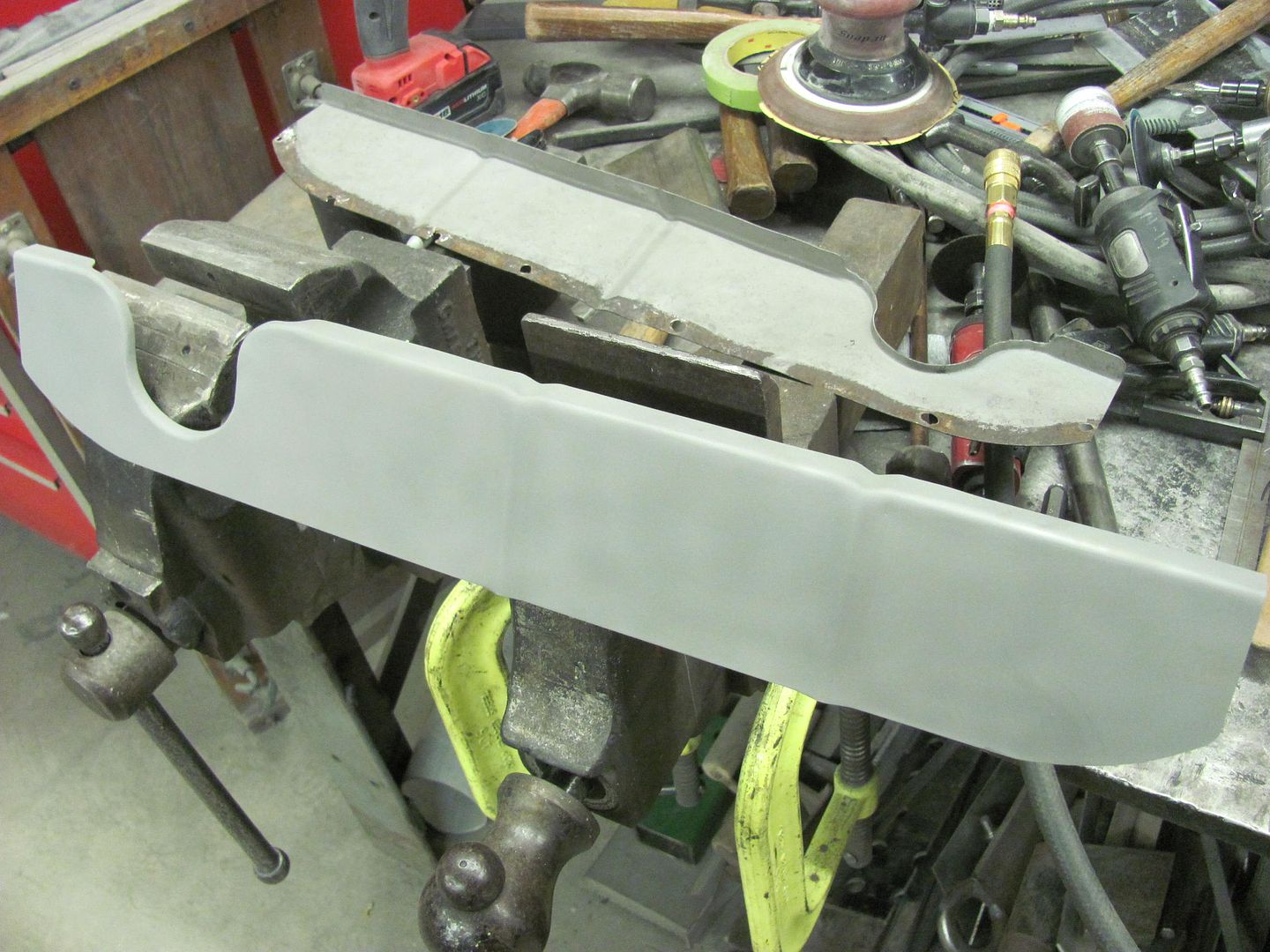 With the core support removed for welding, here with the plug weld holes drilled. 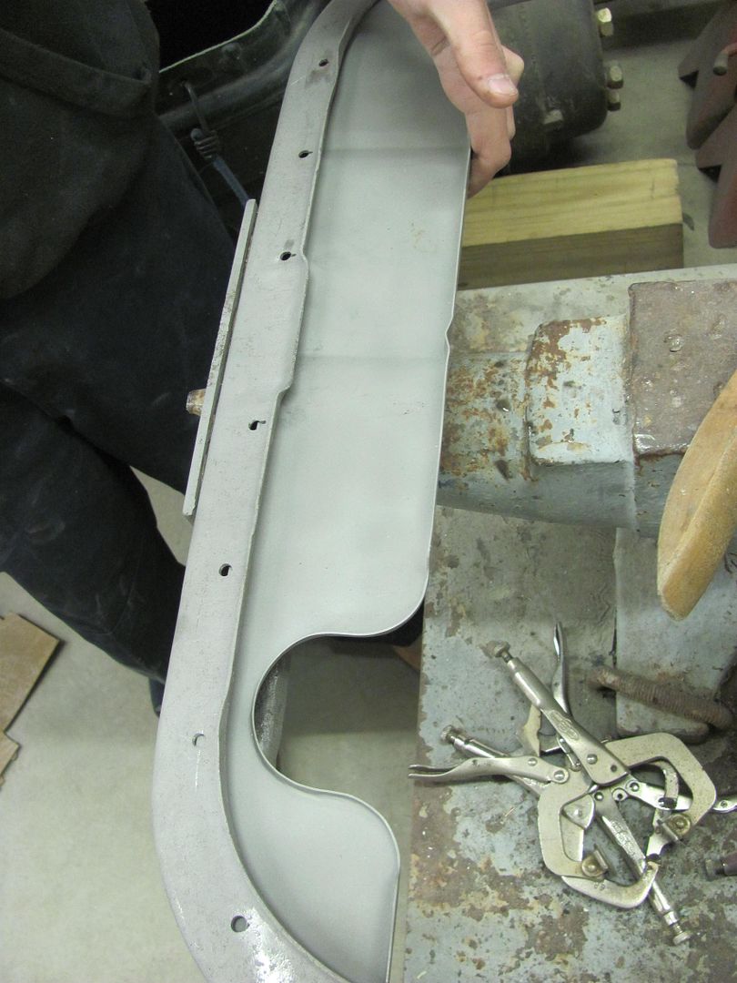 The modified relief we fabricated shows to be about as low as we could have made it.. 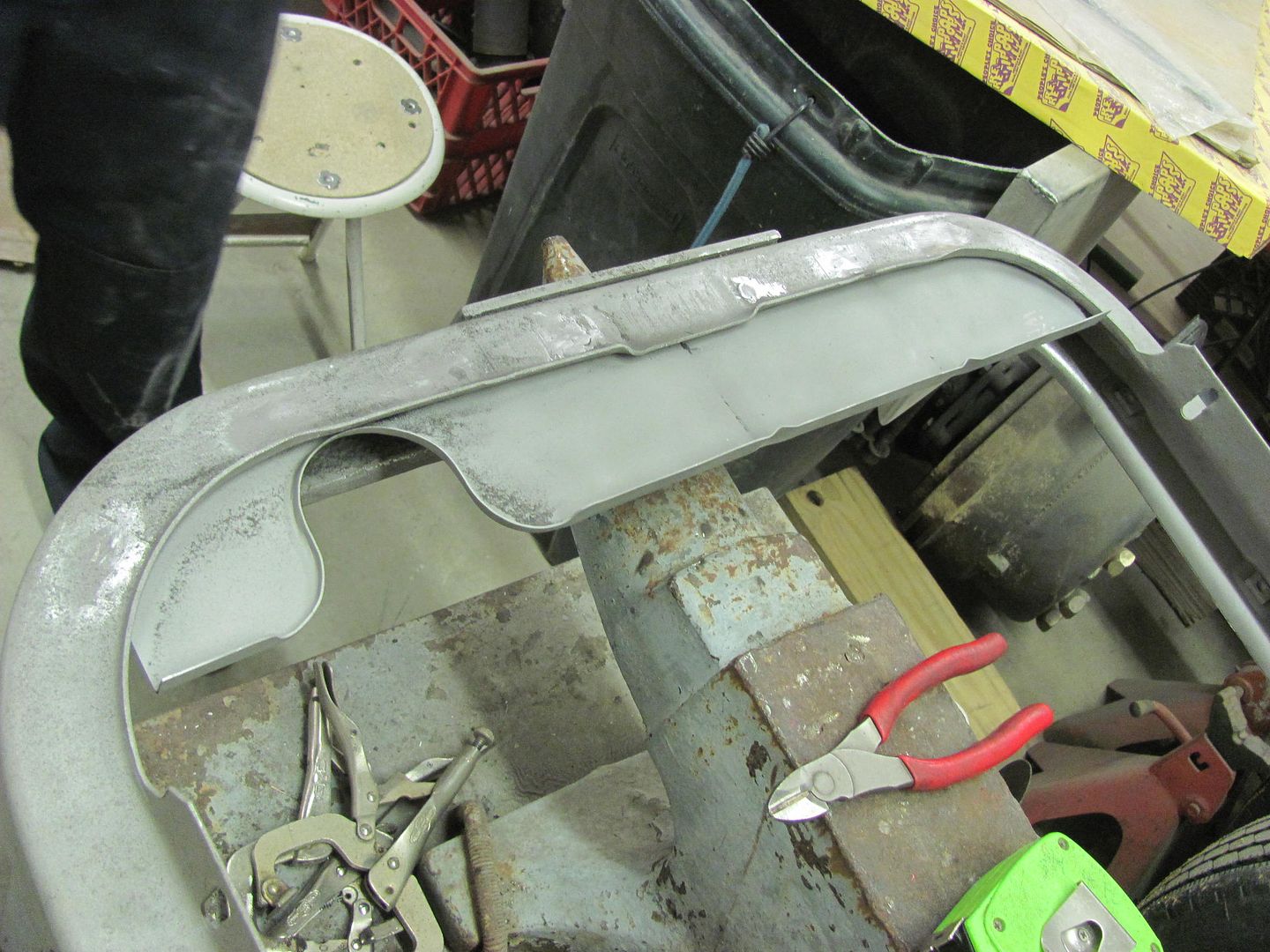 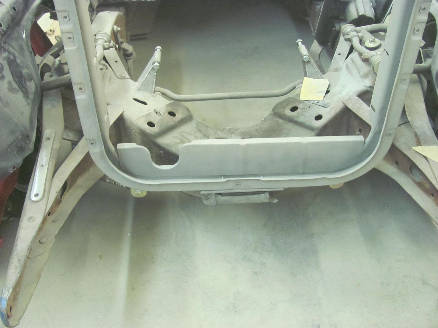 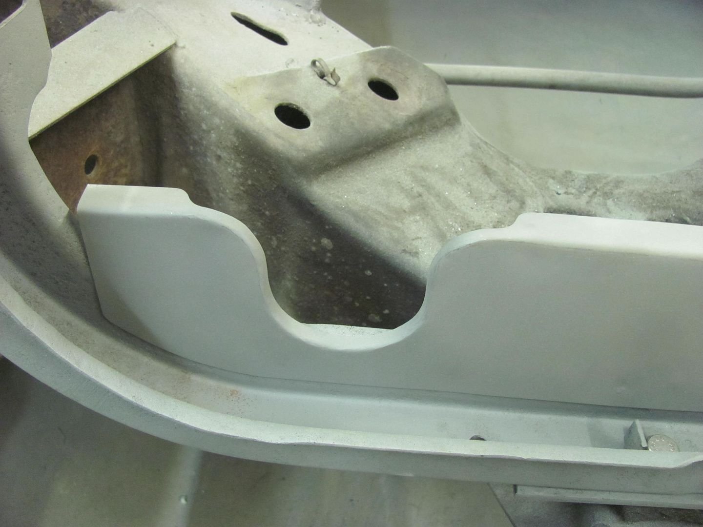
__________________
Robert Instagram @ mccartney_paint_and_custom McCartney Paint and Custom YouTube channel
|
|
#4
04-13-2015, 05:56 AM
|
||||
|
||||
|
Thanks for showing the step by step.

__________________
Marcus aka. Gojeep Victoria, Australia http://willyshotrod.com Invention is a combination of brains and materials. The more brains you use, the less materials you need.
|
 |
| Thread Tools | Search this Thread |
| Display Modes | |
|
|


 Linear Mode

